A friends C370 has recently stopped working and I'm having a look at it now. Apparently it had been running hot for a while then made a few unexpected noises and then switched into protection mode. After being off for a while it will produce sound for a short time before protect mode kicks in again.
So I've measured the resistors connected to the output transistors and these measure 0.7 ohms rather than 0.2 on the schematic. (R370, R352 R354, R349 R353 R355) and I measured the resistors which seem to get hotist (judging from the heat marks on the lid) and these measured 1k5 ohms instead of 2k2 on the schematic. (R334, R344)
The main 10,000uF capacitors look a little bulgy and there is a little staining around their base on the pcb.
I'd appreciate any advice regarding what might be happening and further tests I can do to pinpoint the root cause of the problem.
Attachments
Just in case the image was too small:
An externally hosted image should be here but it was not working when we last tested it.
" ... sound for a short time before protect mode kicks in again ... I've measured the resistors connected to the output transistors and these measure 0.7 ohms rather than 0.2 on the schematic. ..."
Age and repeated over range heat will do this = power on/off over several years. Get ready to replace these. Consider a little higher wattage if there is room = 2 watt or 5 watt. "Audiophile quality" recommended, +/- 1% or better.
" ... The main 10,000uF capacitors look a little bulgy and there is a little staining around their base on the pcb. ..."
This may be serious. Consider replacing these with modern audiophile type caps.
You might also try to figure out where the excess heat is coming from, specifically. Power supply? PS caps warm? Outputs over heating? The first audio stage(s)? Left side or right side or both, equally?
Fix the heat problem first before upgrading elsewhere. Also measure the voltage across the Zeners (TL431 time 2 times two channels = http://www.fairchildsemi.com/ds/TL/TL431A.pdf ). This voltage should be equal on each channel and on left & right. One of these running outta spec could be the culpret. (These are adjustable, according to the schemo, but after adjustments to factory specs, none should be more than 5% variation.)
I'm unsure what would classify as "Audiophile quality" and the only 1% 0.2r I've found is rated at 3W
Vishay LVR-3
Is wirewound appropriate in this position?
Vishay LVR-3
Is wirewound appropriate in this position?
" ... Is wirewound appropriate in this position? ..."
I would not use wire wound resistors anywhere near a signal path 'cause you don't know how the inductive component of these will act or react to the other associated components = wire wound resistors are just that = a coil of resistance wire wound around a form = an inductor.
There are plenty of places for wire wound resistors, like in the current / power path of a power supply where these can actually be benifitial to the purpose = remove a little of the noise from the power path, but in the signal path, these can remove some of the audio signal as well ...
" ... I don't know what would constitute an "audiophile grade" of these. ..."
I use the term relative to the low cost, lower performance "ordinary" components. "Audiophile quality" and "Golden Ear quality" are very relative terms used in this case to distinguish between the ordinary.
In the case of capacitors, there are many ranges of quality of result. For the purposes of power supplies, as in this example (the NAD amp), one could add smaller value polystyrene caps in parallel with the bigger electrolytic caps and achieve similar results in improvement of performance approaching "audiophile quality" = better response to higher frequency noise components in the power supply ...
"Truth is one, paths are many ... " - The Dalai Lama ( http://www.dalailama.com/ )
Ignore the "Audiophile Grade" comments. I think the aim here is to get it working. Metal Film resistors will do.
If the resistors are Fusible, you can use regular ones but only to TEST with... the idea obviously is that the fusible resistors protect from serious damage/fire by going open circuit if too much current flows.
If the resistors are Fusible, you can use regular ones but only to TEST with... the idea obviously is that the fusible resistors protect from serious damage/fire by going open circuit if too much current flows.
Be carefull trying to measure 0.2 ohm resistors. The reliable ways are:
A 4-wire ohmeter
An ohmeter with a zero adjust
Measure the voltage across the resistor and the current through it
and compute the value of R.
The way fusable resistors are made, they usually fail completely open.
Metal film resistors can puddle. Carbon composition resistors usually get larger in value when they fail.
" ... think the aim here is to get it working. Metal Film resistors will do. ..." ")
" ... [use a] A 4-wire ohmeter [and/or] An ohmeter with a zero adjust ..."
Be sure you know where the hot spots in the circuit(s) are first and take action to fix this ... then check all the caps for leakage (or replace if hot or suspicious operation) ... then the resistors should be done last, unless there are some obvious candidates (or replace, wholesale, if hot or suspicious operation).
I went ahead and replaced the capacitors that looked to have leaked or bulged as well as the 2k2 resistors that were under value. I also changed the tl431 because testing in circuit was difficult.
I then checked the output offset, the idling current and the impedance sensing circuit sensitivity as per the service manual. All were fine.
However I still have only a minute or two before the amp switches into protection mode.
I'm a little puzzled by the delay before the protection mode kicks in and unsure what to do next. Any pointers appreciated.
So I assume that testing the output transistors in circuit is tricky so I would now have to remove and test individually?
Or just get a complete set of pairs. Would the transistors have failed in relation to the failing capacitors or would I be looking for another cause before fitting the new parts?
Or just get a complete set of pairs. Would the transistors have failed in relation to the failing capacitors or would I be looking for another cause before fitting the new parts?
" ... I assume that testing the output transistors in circuit is tricky so I would now have to remove and test individually? ..."
Yes .. and mark 'em as you remove 'em so you can identify which turns out to be "bad" or not ... and that way you won't get the pairs mixed up = keep the matched pairs together.
If you do find a bad one, it and it's mate should be considered as suspect. Also the components around the bad one(s) should be rechecked, especially the caps, but don't ignore the resistors = a bad cap or resistor close to a bad transistor could have been the original culprit ...
If desoldering is involved around the transistors, then careful attention to the reassembly is is in order = looking for cold joints and shorted solder pads ...
Lots of work, but that NAD is a keeper = decent audio gear worth keeping and using for years.
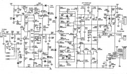
From the diagram: http://www.diyaudio.com/forums/attachment.php?s=&postid=1155178&stamp=1173630640 ...
Left amp only pictured: it looks like Q317, Q321, Q323 (+ side) match up with Q322, Q324, Q327 (- side), respectively, PNP to NPN = matched pairs.
The physical location of these will tell you more about which matches which than the diagram ...
There is also a possibility that the error / short circuit / thermal protection schemes have associated transistors also = questionable ... but those should be checked only if the mains prove to be completely satisfactory. Lastly, if no "bad boys" are evident, then you would debug the first input stage (the onboard 1st level gain stage beginning with Q301 & Q302) ... but that's last and you will probably find the bad boys before you get to that.
Ready for mod suggestions?
The only thing I would do to this ordinarily quite satisfactory amp is make sure that C309, C310, C316, C317 (all 0.1 uF [100 nF]) are of the plastic, polystyrene or MKT type = slightly better than Tants and much better than electrolytics for tighter bass and refined highs. As long as the power supply has not taken a dump or become "strained" 'cause of the hard work of driving bad outputs, etc., then that's about all I would recommend (other than similar suggestions above re: film resistors, etc.) ... Like I say, this amp is a keeper = expensive when new and as good as any at the time = not so long ago.
The only thing I would do to this ordinarily quite satisfactory amp is make sure that C309, C310, C316, C317 (all 0.1 uF [100 nF]) are of the plastic, polystyrene or MKT type = slightly better than Tants and much better than electrolytics for tighter bass and refined highs. As long as the power supply has not taken a dump or become "strained" 'cause of the hard work of driving bad outputs, etc., then that's about all I would recommend (other than similar suggestions above re: film resistors, etc.) ... Like I say, this amp is a keeper = expensive when new and as good as any at the time = not so long ago.
I will do as you suggest regarding the mkt caps, (I'm not sure of the temperature that you can use styrenes up to.)
I have been tempted to use something like panasonic fm or rubycon ZL in the pre sections (if I could get inside the plastic boxes they are glued). I'm I correct in thinking that the low ESR caps are suitable everywhere but immediately after a regulator?
Also the speaker terminals are connected to the motherboard via buzz bar rather that copper wire, I was thinking that can't be doing the signal any favours. But apart from that the amp looks well designed and as if the money was spent on the components inside rather than the packaging.
" ... I'm not sure of the temperature that you can use styrenes up to. ... " = couple hundred degrees F., but don't touch 'em with your soldering iron except around the wire legs = melts the styrene plastic = just like a styrene plastic model airplane ...
" ... panasonic fm or rubycon ZL ..." = Great electrolytic substitutes = about as good as they get.
There are many sources for quality audio capacitor information, some from the manufacturers like Rubycon, etc.
Re: Plastic caps ... Do a search here at DIYAudio.com for "polystyrene capacitor"", etc.
" ... the speaker terminals are connected to the motherboard via buzz bar rather that copper wire, I was thinking that can't be doing the signal any favours. But apart from that the amp looks well designed and as if the money was spent on the components inside rather than the packaging. ..."
Speaker connects to the MB are OK = higher voltage, powered signals are never a serious problem, unless the lines are long > 6 feet or so. ... noise creeps in at the low signal level and through the PSU, etc.
Yes indeed: NAD used to be "the good stuff in the plain brown wrapper" ...
- Status
- This old topic is closed. If you want to reopen this topic, contact a moderator using the "Report Post" button.
- Home
- Amplifiers
- Solid State
- NAD C370 Diagnosis and repair help