Very. Suppose 2 transistors are in parallel. One has an Hfe of 10. The other 110. One will carry most of the current, heat up and you won't be able to compensate for thermal runnaway.
i.e. Repeat
If it heats up, it conducts more then it heats up and conducts more...
Until failure
i.e. Repeat
If it heats up, it conducts more then it heats up and conducts more...
Until failure
hi ostie
two issues here.
first is if you have parallel output transistors.
KISS meant these. I think. Emitter resistors should allow for mis-matched transistors, but to do this theyhave to be big enough to even up the current even if mismatched.
But often a low gain transistor may require a larger Vbe to turn on to the same current as a high gain transistor. The voltage across the emitter resistor has to allow for Vbe as well as gain and so on.
If you purchase several devices at once, you may find they are from the same lot, from the lot number on the package. If so, you may well have die from the same silicon diffusion, and have closely matched gains that modest emitter resistors are adequate.
I think you meant whether the NPN/PNP have to be matched. The answer to this is yes. Self has said that manufacturers often do not bother. This is, he pointed out, because a high open loop gain can handle non-linearities like gain variation in the output stage.
I disagree, and always try to match transistors. Even a "blameless" amp will give lower distortion if the NPN/PNP driver and outputs are matched. It is not always possible to get a good match because NPN and PNP's never come from the same wafer and the next best thing is to try to buy different lots and search. Or maybe, diy-er's might be willing to list gains of their devices and be willing to swap ...
cheers
John
Hi John,
I completely agree with you with regard to matching.
Also consider the crossover point in the waveform. Your emitter resistors will not generate enough voltage drop to reinforce current sharing. The outputs will turn off at different times.
Some transistor compliments match closer than others. This is where the Japanese parts were superior to the US ones. They were faster too (as everyone knows) with a flatter gain vs current curve.
-Chris
Strongly agree with John and Chris.
Only the parallel devices need be matched; you are not advised to match pnp with npn - that's very difficult, as John remarks, it will ensure each half of the output stage has the same transconductance, but in my experience it's difficult to find NPN/PNP beta matches from standard complementary pairs.
Think on what's happening here - parallel transistors share the same bias voltage (usually from one driver per side), and since in an AB amp we might only have a bias around 60mA using a 0.22R emitter resistor, a typical value, the voltage dropped at idle is only 13.2mV. If the base emitter voltage is 600mV, as an example (and they all vary slightly), then 97.8% of the bias output voltage is dropped across the transistor input junction.
This tells us that if another transistor sharing the same input bias has a base emitter voltage of 605mV, only 8.2mV will be dropped across its 0.22R emitter resistor, and this corresponds to a bias level of only 37.3mA, a very substantial difference compared to 60mA passing through the '600mV' transistor.
The solution to this problem is to match beta within about 5%, and match Vbe AT THE SPECIFIED BIAS CURRENT within 1mV. This is my solution, and in the above example though using 0.47R emitter resistors all parallel transistors normally check out at 60mA +/-3mA, which is acceptable.
You will need ten transistors from the same batch for two pairs of matched transistor for both beta and Vbe. You need around 15 for one triple, and around 25 for a quad.
I take up a batch of say 100 devices, and then at 60mA and a fixed collector emitter voltage (I use 6V) I measure the base emitter voltage with an accurate DMM. I then grade devices into Vbe bands. Once all the devices are graded, I pick up one pile, say at 600mV Vbe, and then measure their betas at constant current and voltage. If within 5%, I match them up. I go through all my piles, and then match each pile. It takes about 40 minutes to match up 40 pairs.
You can buy matched pairs and triples for some output devices, as I understand, but you pay a premium. I use 2SC5200/2SA1943 from Toshiba, and buy by the thousand. These are very good, tight tolerance transistors.
Anecdotal evidence suggests that open loop distortion of devices so matched is around ten times less than unmatched. This has profound effect on the final, closed loop THD.
Cheers,
Hugh
Thanks guy to take some of your precious time to answer.
This is because I had a discussion with another member on another forum and he said that this is not important to match output pair.
For me, I think this is important and I always try to match them, at least for the Hfe. But would like to know if I'm doing this for nothing,
matching NPN and PNP
Thanks again.
Hi ostie01,
-Chris
No. I do this as well, and have for years. The closer everything can match up, the better the amp operates. As Hugh mentioned, this is sometimes impossible (well, most of the time) so just do your best.But would like to know if I'm doing this for nothing,
matching NPN and PNP
-Chris
Hi,
The more important matching is Vbe.
I absolutely agree with AKSA.The solution to this problem is to match beta within about 5%, and match Vbe AT THE SPECIFIED BIAS CURRENT within 1mV.
The more important matching is Vbe.
")
Hello,
I did not found a better thread than this one.
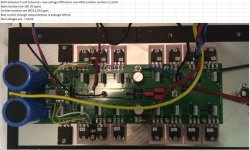
I'm finalising two monoblock amps from which the output stage exists of set 2SK1530/2SJ201 drivers and 7 pairs of Sanken 2SA1386/2SC3519 BJT's.
I've tried matching them within the specs mentioned below.
I have measured each device multiple times, mounted on a big heatsink and only 7volts Vce to minimise thermal influence.
---
AKSA: "The solution to this problem is to match beta within about 5%, and match Vbe AT THE SPECIFIED BIAS CURRENT within 1mV. This is my solution, and in the above example though using 0.47R emitter resistors all parallel transistors normally check out at 60mA +/-3mA, which is acceptable."
---
I than mounted all devices to the PCB and final heatsink and swapped again some BJT's based on my measurement to have better mathing.
Now in the END I have a difference of 1.6mV over the 0R22 emitter resistors, between highest and lowest measurement. The 1,6mV is the same for both P and N devices.
Is this acceptable?
BTW, the base resistors are 10R. (lowering them had negative impact on stability)
I did not found a better thread than this one.
I'm finalising two monoblock amps from which the output stage exists of set 2SK1530/2SJ201 drivers and 7 pairs of Sanken 2SA1386/2SC3519 BJT's.
I've tried matching them within the specs mentioned below.
I have measured each device multiple times, mounted on a big heatsink and only 7volts Vce to minimise thermal influence.
---
AKSA: "The solution to this problem is to match beta within about 5%, and match Vbe AT THE SPECIFIED BIAS CURRENT within 1mV. This is my solution, and in the above example though using 0.47R emitter resistors all parallel transistors normally check out at 60mA +/-3mA, which is acceptable."
---
I than mounted all devices to the PCB and final heatsink and swapped again some BJT's based on my measurement to have better mathing.
Now in the END I have a difference of 1.6mV over the 0R22 emitter resistors, between highest and lowest measurement. The 1,6mV is the same for both P and N devices.
Is this acceptable?
BTW, the base resistors are 10R. (lowering them had negative impact on stability)
Attachments
Strongly agree with John and Chris.
Only the parallel devices need be matched; you are not advised to match pnp with npn - that's very difficult, as John remarks, it will ensure each half of the output stage has the same transconductance, but in my experience it's difficult to find NPN/PNP beta matches from standard complementary pairs.
Think on what's happening here - parallel transistors share the same bias voltage (usually from one driver per side), and since in an AB amp we might only have a bias around 60mA using a 0.22R emitter resistor, a typical value, the voltage dropped at idle is only 13.2mV. If the base emitter voltage is 600mV, as an example (and they all vary slightly), then 97.8% of the bias output voltage is dropped across the transistor input junction.
This tells us that if another transistor sharing the same input bias has a base emitter voltage of 605mV, only 8.2mV will be dropped across its 0.22R emitter resistor, and this corresponds to a bias level of only 37.3mA, a very substantial difference compared to 60mA passing through the '600mV' transistor.
The solution to this problem is to match beta within about 5%, and match Vbe AT THE SPECIFIED BIAS CURRENT within 1mV. This is my solution, and in the above example though using 0.47R emitter resistors all parallel transistors normally check out at 60mA +/-3mA, which is acceptable.
You will need ten transistors from the same batch for two pairs of matched transistor for both beta and Vbe. You need around 15 for one triple, and around 25 for a quad.
I take up a batch of say 100 devices, and then at 60mA and a fixed collector emitter voltage (I use 6V) I measure the base emitter voltage with an accurate DMM. I then grade devices into Vbe bands. Once all the devices are graded, I pick up one pile, say at 600mV Vbe, and then measure their betas at constant current and voltage. If within 5%, I match them up. I go through all my piles, and then match each pile. It takes about 40 minutes to match up 40 pairs.
You can buy matched pairs and triples for some output devices, as I understand, but you pay a premium. I use 2SC5200/2SA1943 from Toshiba, and buy by the thousand. These are very good, tight tolerance transistors.
Anecdotal evidence suggests that open loop distortion of devices so matched is around ten times less than unmatched. This has profound effect on the final, closed loop THD.
Cheers,
Hugh
AKSA is totally on point on this one.
- For same flavor Output devices, matching VBE is by far the most important. The more mismatch, the higher the RE needs to be which has other problems. BUT, the most important this is to match VBE's over temperature. I.e. the parallel output devices need to be thermally coupled, hence why they are mounted on the same heat sink. Else, temperature differences will cause the VBEs to drift apart, the hotter device will have the smaller VBE, hog all the output current and potentially blow up.
- Beta match is important too because of the output device base resistors. Look at the HoneyBadger amplifier, each output device has 2.2 ohm base resistor. The voltage drop across these adds to VBE since the output devices are biased with a fixed VBIAS spreader. Therefore, if beta mismatches you are indirectly adding VBE mismatch to each device, which takes us to the previous paragraph.
Hope it helps.
Best, Sandro
Hi Sandro,
Nope. Beta is critical whereas vBE will naturally be close. Even if it isn't, the current through the emitter resistor will swamp vBE differences very quickly.
The only thing I can figure is that measuring vBE is easy and so that is what people want to do. Take the easy way out. But vBE will mislead you, so do it right and measure beta while keeping the parts at the same temperature. I had to build jigs to do that.
-Chris
Hi Chris,
Can you explain the why of: "Beta is critical whereas vBE will naturally be close"?
VBE:
-VBE match at quiscent is as good as you get them from the manufacturer.
-VBE match over temp is as good as your heatsink and thermal coupling.
But, I do agree the RE resistor mitigates the problem a lot ... so that is settled.
Now, why do you think Beta matters that much? The only mechanism I can think is through the base resistor as I explained. What am I missing?
- Sandro
Hi Sandro,
Beta controls emitter current more than vBE does. It is also very sensitive to temperature. So, if you match beta, vBE will be very close anyway.
After over 40 years experience in audio service, and over 30 years looking at matching and its effects, I've been able to distill what actually happens in the real world. Lots of experimentation with many different designs of output stages over the years. I just paid attention to what I was doing while doing my work, resulting in a decades long experiment. My designs have supported this view as well.
-Chris
I have experienced in the last couple of days exactly as Anatech explains.
I have measured both hfe and Vbe on a small matching tool made on a perf board.
When listing everything (50 bjt’s) in a spreadsheet, I directly noticed that same Vbe parts had same hfe, very consistently.
I have measured both hfe and Vbe on a small matching tool made on a perf board.
When listing everything (50 bjt’s) in a spreadsheet, I directly noticed that same Vbe parts had same hfe, very consistently.
Last edited:
Hi Chris, I hear you and I do not doubt your observations, but without a technical explanation it does not really help me understand the issue, i.e. the WHY for the observations.
Now: Beta controls emitter current more than vBE does.
That is true if you are driving the transistor with a base current: IE = (Beta + 1)*IB.
If you are driving the transistor with a voltage then IE = IS*exp(VBE/(KT/q)) * (1+1/Beta)
- IF RSource = 0, beta does not matter much (if beta is 10 it is a 10% adder to IS*exp(VBE/(KT/q)+1)).
- IF RSource != 0, then you get a term due to VBE reduction: IE = IS*exp((VBE-IB*RS)/(KT/q)) * (1+1/Beta) which introduces a dependency.
Now in the case of the output devices.
- At quiescent, IE is determined by VBIAS, i.e. voltage drive. Rsource is non-zero due to the base stopper resistors and 're' of the drivers, so there is a beta dependency but I already mentioned this one, so nothing new.
- At signal, IE is determined by the load, not Beta. Assuming even distribution:
IE = Vout / RLOAD / Number of parallel devices.
The actual distribution of the current across devices is determined by VBE at temperature match and RE match. I already talked about this above so I am not repeating.
Hence, beyond my explanation of beta dependency due to the base stopper resistors voltage drop, I don't know why beta match is critical. Note that internal rb is in series with the base stopper resistors.
Best, Sandro
Last edited:
I have experienced in the last couple of days exactly as Anatech explains.
I have measured both hfe and Vbe on a small matching tool made on a perf board.
When listing everything (50 bjt’s) in a spreadsheet, I directly noticed that same Vbe parts had same hfe, very consistently.
Interesting, but it is not always the case. I.e. VBE_1=VBE_2 does not guarantee Beta_1 = Beta_2.
Hi Sandro,
I'm a working technician, and right now that is what I am doing. I don't get paid to take one person at a time and train them, and I can't afford to do that. Even if I did, it is a very inefficient use of time for both of us.
I have given you the results of a lot of testing, and it agrees with my formal education as well (Ryerson in TO). If you have any formal education, then put it to use and figure it out. Look at the dynamics of an output stage processing a signal. Then, as a sanity check, do the experiments. That might add up to 0.001% or less of what I have done over the years. Probably less. If you don't have a formal education, do the experiments. I'm not going to educate you beyond what I have.
I also designed a transistor matching jig and gave it to our members. It's in an Adcom DFA-565 thread near the end I think. Board layout is there as well as the schematic. The premise behind matching is the same between power and signal transistors, so that might help you. Build the jig and use it, my gift to everyone.
-Chris
Hi Chris, bottomline is you don't know the answer which is fine. Given you are not engaging in a technical discussion, I am going to assume that you are not interested in understanding the underlying cause for the observed behavior which I want to re-iterate I am not calling into question.
- Sandro
P.S. Given you keep quoting your credentials, this is a link to my linkedin profile:
https://www.linkedin.com/in/sandro-herrera-93b94312/
- Sandro
P.S. Given you keep quoting your credentials, this is a link to my linkedin profile:
https://www.linkedin.com/in/sandro-herrera-93b94312/
- Status
- This old topic is closed. If you want to reopen this topic, contact a moderator using the "Report Post" button.
- Home
- Amplifiers
- Solid State
- If you put new output transistors, class A/B, will tou match them?