Hmmmm this one seems to be very good.
Have you constructed this one dear Graham?
The reason of my question was because a friend came to me and asked if i had constructed the last GEM,...that one with the choque, the enormous coil in series with the output line...the upper rail load.... and i perceive that he will not construct, as i told him that i personally had not constructed that last design.
I told that i did not have listened to that one....but also i told him that one Brazilian had assembled, Eddie Eayoama, and it may be reproduccing the unit to close friends...he said sounded great.
But i have not made exactly that last one...mine was another one... and this made my friend give up....this is a very sensitive matter as i could see...people want a complete guarantee...and this can be given if the unit was tested real world and subjected to heavy and continuous testing.
I have perceived that people trust, a little bit more, in those already tested real life amplifiers....and this is the reason of my question about this one.
It seems that you have simulated it only.... this do not turns the amplifier bad...as it is clearly good...but may reduce people trust on it.
I will tell you about another forum...hehe...more an Prisional institution, where banished people are there making noises...and other good people too....those guys loves brand new ideas...i think they will love your circuits.
I was almost kicked out from there...one single bad educated guy, but all moderators entered and used the long arm of the law...i loved that...they are Police!..the way i always dream about moderators.
there are many good here....Weldon is fair...SY is an supersonic figther, Anatech is friendly, Planet 10 has a chinese patience..well...Variac is kind...we have a lot good here...but those there hold a double barreled and shot clearly between the eyes....GREAT!
am i wrong?
regards,
Carlos
Graham Maynard said:This topology could be modified to become an audio amplifier, a headphone amplifier, a line driver or preamp.
Shown here as 8 ohm class-A which should sound first class.
Graham,
That's an interesting circuit for sure. I like people that go into uncharted terrain! I see a lot of opamp techniques in it. The abundance of large elcaps isn't too attractive but possibly that can be reduced in further evolution. What I wonder is how the thermal stability is like? Any thermal feedback necessary between the bias setting current sources and the output stage?
Jan Didden
Hi Carlos,
This circuit is based on buffers that have already been constructed and are running with the GEM amplifier. They SOUND good.
No not built - just out of my head today.
Many folk seem wary of the choke in my 100W GEM design. Sonically it works just fine. It is fully tested and fully satisfies me.
Daniel Bosch in S Africa has built several 200W GEMs with the CCS class-A load, and says he is going to sue me - for 'time'. He uses them with ordinary LS and Apogees, and says that once he starts listening - he can't stop !!!
Hi Jan,
My thoughts are that the single bias setting transistor could be thermally coupled to a heatsink for power amplifier design.
Here would be a 600 ohm line driver version running from regulated +/-24V rails. VERY low distortion. 12dB gain. 100k input impedance.
Attachments
Graham Maynard said:Hi Carlos,
This circuit is based on buffers that have already been constructed and are running with the GEM amplifier. They SOUND good.
No not built - just out of my head today.
Many folk seem wary of the choke in my 100W GEM design. Sonically it works just fine. It is fully tested and fully satisfies me.
Daniel Bosch in S Africa has built several 200W GEMs with the CCS class-A load, and says he is going to sue me - for 'time'. He uses them with ordinary LS and Apogees, and says that once he starts listening - he can't stop !!!
Hi Jan,
My thoughts are that the single bias setting transistor could be thermally coupled to a heatsink for power amplifier design.
Here would be a 600 ohm line driver version running from regulated +/-24V rails. VERY low distortion. 12dB gain. 100k input impedance.
How about making that 22 ohms into 2 x 11 ohms, couple the output from the tap, and replace the two 4m7 caps with a single 2m2 across the 2 x 112 ohms? Would that work? Apart from the offset, that can be dealt with cheaply anyway.
Jan Didden
janneman said:How about making that 22 ohms into 2 x 11 ohms, couple the output from the tap, and replace the two 4m7 caps with a single 2m2
that's actually not completely equivalent, the 11 ohms are in series with the output impedancesof the top and bottom half of the buffer, whereas in the original schematics the 22 ohms is AC bypassed. However, given there is already a series resistor after that, one could use this fact to eliminate it.
The way this buffer derives it's quiescent curent reminds me strongly of the MF A1 amplifier. It also used a symetrical layout where the halves are conencted via resistors, and each half has a DC bias introuduced, in order to have a defined quiescent current through the connecting resistor.
The only slight complait i have with this is about the 'balanced' - to be honest, reading the title, i was expecting a differential driver
")
Hi Jan,
The connection you describe has been tried, and is not used because the amplification of errors causes variable offset with temperature.
When driving a low resistance load the offset becomes an imbalanced current flow which becomes audible as increased distortion, thus could be set cold and become worse after an hour or so, or be set hot and then take time to come good.
All capacitors are correctly biased and as you surmise - the signal path ones do not need to be of high working voltage.
Back to back low ESR electrolytics at input have also been tested here for sonic signature and none has been noted.
Hi lumanauw.
Large value Cs have not concerned me. Without needing to say I trust that everyone would use low ESR types and always parallel high value components with reducing values ones.
Thus my 4m7F would actually be 4,930.47uF if I added all the labelled values together.
Hi ilimzn,
Maybe I should have written complementary-balanced. Do please note that I have deliberately avoided using a differential pair with any kind of tail or mirroring in order to minimise the number of stages (phase shift) enclosed by the NFB loop.
Just noticed that in my hurry yesterday I had the feedback capacitors connected the wrong way round.
I have also added feedback resistor gain options to show versatility for pre-amp or line driver usage.
As stated before with the first circuit, can also be used to drive phones or LS, and can be run in a more powerful class-A arrangement.
I have also added feedback resistor gain options to show versatility for pre-amp or line driver usage.
As stated before with the first circuit, can also be used to drive phones or LS, and can be run in a more powerful class-A arrangement.
Attachments
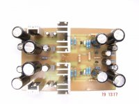
The last circuit above eventually became this, and initial testing is reported as sounding excellent. The better a circuit is, the harder it becomes to detect any flaws which might exist, so many longer listening tests are now required.
Input towards the centre-right in this photo. Output is small island between heatsinks. +/-24V regulators are at left top and bottom.
Input R and gain selection may be switched or relay operated. The intention being to make the circuit universal. Actually a dual 1k pot could be used to adjust gain and make this a useful benchtop signal amplifier. It also drives phones or a small LS as-is, though for more serious phone work I would suggest reducing the value of the 10 ohm series output resistor to 1 ohm. This resistor might be removed if output shorts can be ruled out
Cheers ......... Graham.
Attachments
- Status
- This old topic is closed. If you want to reopen this topic, contact a moderator using the "Report Post" button.
- Home
- Amplifiers
- Solid State
- Simple balanced driver circuit.