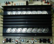
Because the big size of the schematic, yet i have not achived to convert this in jpeg to upload. I enclose a photo of this power amplifier module, a photo of the plan, and finally a zip fille with the drawing. May pointed out, that this module has presented already in my previous thread "wow!a beautifull preamplifier module" but for a different reason. Anyhow in this, you can see some oscillograms of his performance.
Attachments
Oh pain...i have not the CAD program...oh pain!
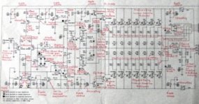
It seems to be interesting...very interesting.... as you already know, the schematic is unreadable, even using digital processing.
Having in PDF, standard adobe files, please, upload it to me:
nanabrother@yahoo.com
regards,
Carlos
It seems to be interesting...very interesting.... as you already know, the schematic is unreadable, even using digital processing.
Having in PDF, standard adobe files, please, upload it to me:
nanabrother@yahoo.com
regards,
Carlos
Attachments
Re: Oh pain...i have not the CAD program...oh pain!
If you have a CAD/CAE program, as i suppose because i have see your amplifier already, i can mail you the plans in Gerber.ASCII format.
Regards
Fotios
Yes shure, this is a good way, with e-mail. I post the plan as soon as possible. Also me i have thinked to break the schematic in 3 parts. But needed to go from the begining.destroyer X said:
It seems to be interesting...very interesting.
Having in PDF, standard adobe files, please, upload it to me:
nanabrother@yahoo.com
regards,
Carlos
If you have a CAD/CAE program, as i suppose because i have see your amplifier already, i can mail you the plans in Gerber.ASCII format.
Regards
Fotios
Thanks pinkmouse, i tried to this from yesterday. It is some difficult to me. Thanks.pinkmouse said:I'll have a look and see if I can pdf it up.
Fotios
The PDF document.
An externally hosted image should be here but it was not working when we last tested it.
Dirty Harry PDFSorry for the confusion, but because I have made this drawing before 5 years, I forgot certain important changes. These are:
R3 = 220R and no 390R consequently tail current from 1,7mA becomes 3,18mA
R4, R17, R15 = 2K2 and no 1K
R11, R16 = 22K and no 33K
R9, R10 = 33R and no 56R consequently each emitter of current mirror has 0,87mA
PR1 = 500R and no 2K because MJE340
R20 = 680R and no 390R
R21 = 470R and no 1K5
Output inductor: 15 turns of copper wire d=2mm/core d=10mm
This moment I search for layout. I will make little time to find it.
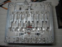
Also the PCB is double sided and her back photo is attached.
I remind that in my thread “wow! a wonderful preamplifier module” there are the oscilograms. If you want inform me to transport those in this thread.
For this amplifier, I have also drawn and constructed the following:
Power Supply, Output protection, and finally a dynamic limiter of the input signal. I forgot also to mark the Resistor of input; this is a Log potentiometer of 50KÙ.
Thus the input impedance is about 50KÙ.
To be continued
Fotios
R3 = 220R and no 390R consequently tail current from 1,7mA becomes 3,18mA
R4, R17, R15 = 2K2 and no 1K
R11, R16 = 22K and no 33K
R9, R10 = 33R and no 56R consequently each emitter of current mirror has 0,87mA
PR1 = 500R and no 2K because MJE340
R20 = 680R and no 390R
R21 = 470R and no 1K5
Output inductor: 15 turns of copper wire d=2mm/core d=10mm
This moment I search for layout. I will make little time to find it.
Also the PCB is double sided and her back photo is attached.
I remind that in my thread “wow! a wonderful preamplifier module” there are the oscilograms. If you want inform me to transport those in this thread.
For this amplifier, I have also drawn and constructed the following:
Power Supply, Output protection, and finally a dynamic limiter of the input signal. I forgot also to mark the Resistor of input; this is a Log potentiometer of 50KÙ.
Thus the input impedance is about 50KÙ.
To be continued
Fotios
Attachments
richie00boy said:fotios if you can save as PNG or GIF that will be much better readable than JPG which corrupts line drawings.
Just a thought - are the fuses visible in the photo for the output stage or just the input, VAS and driver stage?
The fuses are 8A and for whole the circuit. The supply is +/-82V.
Fotios
Good work Enilsen. Thanks for the support.enilsen said:The PDF document.
An externally hosted image should be here but it was not working when we last tested it.Dirty Harry PDF
Re: Oh pain...i have not the CAD program...oh pain!
Fotios
Carlos is O.K. the pdf of enilsen?destroyer X said:
It seems to be interesting...very interesting.... as you already know, the schematic is unreadable, even using digital processing.
Having in PDF, standard adobe files, please, upload it to me:
nanabrother@yahoo.com
regards,
Carlos
Fotios
This is a blatant rip of a Douglas Self design, even some of the component values on the input stage are the same 
Best regards,
Sander Sassen
http://www.hardwareanalysis.com
Best regards,
Sander Sassen
http://www.hardwareanalysis.com
Banned
Joined 2002
fotios said:A photo of schematic in order to understand his size and the difficalty to convert it from the original *.edb format to jpeg.
fotios said:Here is the zip file, but you need a CAD program to open it because the format is *.dwg created by AutoCAD. Such program except AutoCAD is the Corel Draw. If you can open the drawing, then the image has the better quality.
Suggestion: use autocad and do a fake print (a send file to disk, not to a printer). If you use a Scitex or Apple postscript printer drive, you obtain directly a .ps or .eps file that you can easily convert in a pdf format (and usually is directly openable by program similar to Adobe illustrator. The trick often work also outputting "fake" printing from many spice software programs.
Hi
Piercarlo
- Status
- This old topic is closed. If you want to reopen this topic, contact a moderator using the "Report Post" button.
- Home
- Amplifiers
- Solid State
- A powerFULL amplifier named Dirty Harry