I recently have had a problem with this amp.
Does anyone have a link for a schematic for this amp? or have experience in fixing this amp to give me some idea's. Crown's web site seams to have every other schematic for their macro-tech and micro tech series, (what's the difference anyway??) but not this one.
In a nutshell, one of the OPT's went short, (which I have replaced) but I still have bad distortion coming from that channel (sounds like an amp with one of the supply rail fuses blown).
Unlike other amps which have a 'centre tapped' power supply, these ones seam to have a 'floating' ground and measuring the rails on the cases of the OPT's I get +84 on one side and -5 volts on the other...(bride rectifier is OK)
Any help appreciated.
Ed.
Hi
I would say that you have some damaged driver transistors
In the Output PCB.
also look at the possiblity of more leaky output devices
Have a look at this link to get the schematic you require
http://www.crownaudio.com/gen_htm/legacy/legacamp.htm
I would say that you have some damaged driver transistors
In the Output PCB.
also look at the possiblity of more leaky output devices
Have a look at this link to get the schematic you require
http://www.crownaudio.com/gen_htm/legacy/legacamp.htm
Thanks Anthony. I have already been at that page, and it doesn't actually have a schematic for the 1200, only a service manual which does not include the schematic. I have found a micro-tech 1000 diagram, which I assume has the same internals, but smaller transformers (etc) and I am trying to use that.
I will test the driver transistors and see how I go.
I have aldready seen you web site Anthony and am very impressed with some of your work... Im might give one of them a crack one day.
Cheers.
Ed.
I will test the driver transistors and see how I go.
I have aldready seen you web site Anthony and am very impressed with some of your work... Im might give one of them a crack one day.
Cheers.
Ed.
Thanks DJK.
I happen to aggree. I have just ordered heaps of MPSA42,43's, and MPSA19's...Also the drivers, MJE15030/31's..Not to mention about all the OPT's...(not great on the wallet!!)
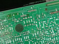
I also found some blown tracks on the main PCB, caused by some shorting diodes (4004's and some 4148's)..I bit of a war zone really, but I will get there..
Cheers.
I happen to aggree. I have just ordered heaps of MPSA42,43's, and MPSA19's...Also the drivers, MJE15030/31's..Not to mention about all the OPT's...(not great on the wallet!!)
I also found some blown tracks on the main PCB, caused by some shorting diodes (4004's and some 4148's)..I bit of a war zone really, but I will get there..
Cheers.
Attachments
All but the outputs are cheap.
For outputs I generally use MJ15024/25 that I buy in 100 lot, so they are only $2.50 each.
Consider adding the last set of outputs if you intend to keep it a long time, I do this on the 600s and 1200s (and change the emitter resistors to suit).
For outputs I generally use MJ15024/25 that I buy in 100 lot, so they are only $2.50 each.
Consider adding the last set of outputs if you intend to keep it a long time, I do this on the 600s and 1200s (and change the emitter resistors to suit).
i do a lot of pro-audio repair, and i have the dubious honor of telling customers that their amp is NERTS (not economically repairable) when i see a lot of traces evaporated from a board (sometimes so rapidly that they don't even leave much in the way of burn marks!!!!!!)...... needless to say pro-audio equipment gets abused worse than home equipment, and i see a lot of hopeless amps.
the other tech where i work had one on the bench today that has a very strange design, in which the collectors of the output devices are all grounded, and the emitters "walk" the floating power supply rails, and couple the voltage changes to the speakers through the filter caps......
the other tech where i work had one on the bench today that has a very strange design, in which the collectors of the output devices are all grounded, and the emitters "walk" the floating power supply rails, and couple the voltage changes to the speakers through the filter caps......
djk wins the flying fickle finger of fate award..... it was a QSC amp that had that oddball output stage...... yes, there are others (including a peavey amp iirc) that actually "drive" ground, and tap off the speaker line at the p/s transformer center tap.... it seems some engineers just can't get enough of trying something different, and putting it in mass production just "because...."
don't get me wrong..... audio is the domain of the experimenter...... but i really don't see a particular advantage to a driven ground vs a "normal" output stage...... but then again, there are times i think outside the box, and other times i don't........ i think driving the rails like on that QSC is really outside the box, but it works, and if a transistor shorts on the positive rail, it doesn't look like it would take any negative rail devices with it, possibly the same is true of a driven ground amp as well.......
in talking with the other tech, i realized something about amp design (especially solid state) that i grasped that he had difficulty with, and that's the concept of current sinks, as opposed to current sources. the other tech does mostly tube amps, and so sees most active devices as current sources. with solid state devices, many active devices act (or can be better understood) as current sinks. especially when working with split supplies, to think in terms of unidirectional current flow can actually cause confusion in the understanding of what is going on in a circuit. i understand full well that electrons flow from negative to positive, but there are times, when analyzing a circuit (especially a symmetrical one with a split supply), that my mind has to follow Ben Franklin's concept of "conventional current" to make sense of what is going on in the circuit..... maybe this is just an example of one of the ways i "think outside the box", or maybe i'm just a little "out of my mind", but it does help with troubleshooting.......
Hi, I also have a similar problem with my Crown 1200 lx. Can you show me what steps I should go about repairing my amp? My amp will not power "On". I've checked the fuses and they seem to be okay. If you could point me in the right direction and if possible a picture to where I might can start looking for the short, maybe than I could fix it on my own. Thank you very much.
One of the advantages of a "rail swinger" amp like QSC's etc, is that should there be a catastrophic failure. like a blown output device. no DC makes it to the speaker!
The crown amps sort of work like this. 2 amps channels, one channel has no ground. the other channels output is grounded. when idle. channel 2 balances the power supply rails.
when in operation. channel 2 swings channel one around by the tail(aka ground) this allows channel 1 to swing fully rail to rail.
a conventional amp can only swing from "0" to one rail or the other. but a CGB amp can swing fully from the Negative rail to the positive rail.
So if you rails were +/70volts lets justs ay for an example. a conventional amp could swing +70v and -70v. but with a CGB amp and the same power supply, it can swing +140V and -140v! doubling the rail swing all by swing the ground around.
so trouble shooting these amps, you really have to understand how they work. the Low side of the amp is the ground swing side. the High side is the actual amp side. if your rails for the amp side are off at idle, you have a problem in the Low side.
It took me a while to wrap my head around it. i stared at a full page schematic for hours and suddenly it all clicked into place how it works.
Of note. also check all the output devices for rust between the TO-3 device pins and the heatsink/chassis. I worked on more than a few of these that lived in night clubs ingesting smoke/fog juice all night and they all developed weird problems with time. after i found many devices that would short to the chassis due to rusting. some legs just rusted in half etc. not a very common thing but. it can happen.
Zc
Hi Ed.
Conventional bridging amplifiers are two conventional amplifiers (with grounded power supply center taps) driven in opposite phase with the loudspeaker load connected between both outputs - ie both speaker lines are active wrt to system earth.
In the Crown/Amcron approach one amplifier stage drives the speaker lines in the conventional manner (one line active, other speaker line tied to system earth) and the second amplifier stage swings the supplies wrt to system earth.
This approach removes the problem of both speaker lines being active.
Eric.
Looking for: Schematic for Crown MT 1200???
Hi Cool Zero,
Thanks for the reply. Would you have the schematic for the Crown MT 1200? I would like to understand the schematic than maybe like you, I could fix mine. I am a beginner at fixing amplifier but I am very interested and determine. I have just recently discovered the Crown MT amplifier and I am very impress with the power that these amplifier can put out. I was told to check all the transistors so that is what I'm doing now. I will post again if nothing is fixed. And hopefully repair it.
Thanks
P.S
I like your quote! " It's not about what you can BUY...It's about what you can BUILD!"
Hello
I have my rental company and we have a few Crown amps as well. Some of them were burnt out so here comes my experience by fixing them. They are all build around same principal circuit. You have to check all output devices on both hot and cold side. You have to check all 4 drivers 2 for hot and 2 for cold side of each channel. On MA amps these are mounted separate on small vertical sinks mounted with metal clamps....and check all diodes on the output boards as well. It is wise to check all of emitter resistors if they are still there. I fount that in most cases burns cold side of each channel. Please check all those elements and when you find out what is wrong use just 2 transistors for hot and 2 for cold side and start up the amp which should work without distortion. For this experiment are good old transistors. After that it is important to replace all outputs with new devices 15024/25 and adjust the idle current for cold and hot side separately. It is waist of time and money just replace outputs and plug it in the power because if you don't repair everything it is quite possible to burn new set as well. Be aware of HIGH VOLTAGES present in the amp. Once again. On my experience is almost certain that some of outputs are burnt. It cause quiet and distorted sound. Sometimes amp works but it runs too hot at low levels as well. Almost never is wrong something on signal input big board. I have only once such case when input was overdrived and after that I discovered that amp falls into strange hiss mode......it was burnt input op amp.
Best regards
Taj
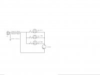
Tajzmaj;2526039It is waist of time and money just replace outputs and plug it in the power because if you don't repair everything it is quite possible to burn new set as well. Taj[/QUOTE said:Try using a light bulb box when you test the amplifier. It limits the short circuit current to what a pair of output transistors can handle.
Attachments
- Status
- This old topic is closed. If you want to reopen this topic, contact a moderator using the "Report Post" button.
- Home
- Amplifiers
- Solid State
- Amcron (Crown) Micro-Tech 1200 help