Hi Tom,
In some stages, matched resistors are required. Good that you have noticed this!
Congrats on your successful kidney transplants (they last one is a keeper I hope). My cousin has gone through four rejections now, it started when she was in her early 20's. Suffice to say that life pretty much sucks for her. Through all of this, she has held down her own job, bought and maintained her own detached house with no hubby to help her at all. That girl (lady) really deserves a break. I think she just gave up and went off her diet. Can't say as I blame her, she'll be around 50 years old by now. A real trooper and nice to boot.
You have my respect, having gone through some unpleasant times.
Now, back onto the complimentary differential pair you were talking about. All four transistors must be tightly matched to get great performance from these types. That would be SAE, Adcom, Phase Linear, Bryston and a host of others. Do that right and everything else will fall into place. Low DC offset, low distortion and much better sound.
If you get these transistors matched tightly, the match on any resistors in the emitter circuits begin to have an effect. That is a sign of things going right. If these resistors are not matched and they do not affect the offset much, the transistors are not matched close enough for a really good job.
-Chris
Thanks Chris,
Yes, I started at age 23. I turned 48 2 day's ago. It's been Really tough. My sister started with this at age 11 in 1980. She has had 2 also. She has died twice 2.5 min & 4 min. I have had my chances over 14 times now. My sister & I are both married. It is a rough life, and never certain. I got into bodybuilding, which has helped me more than anything I have done. Give you cousin my best, and tell her to keep pushing forward... Sorry for the Hijack Echo... I'll use the E'mail feature next time...
Love that SAE gear!!!
Best Regards, Tom
Hi Tom,
Thanks and no problem. If you want, you could always begin a new thread as well.
My cousin has given up. Most people can't take her going on her dialysis machine. It can be a bit bloody. I try to stay and talk with her through this. It is a bit much for the average person though.
Keeping a marriage together while going through this is amazing. You and your sister have special people as mates. It's harder to watch someone in this situation than it is mentally for the people who are in the situation. Although I have an idea how it might be for you and your sister, and my own cousin for that matter, no one can know what this is truly like unless they are in the same spot.
Take care Tom, Chris
It's terrible on both sides of the fence. I have been there. Before I knew I had the disease, we found out my sister had it. The doctor told us, "people with this disease, don't usually live very long lives"... I was mortified. When my sister got her transplant in 1981 I ended up with post traumatic stress syndrome. Then I got the disease. I was only 23, so I didn't have a job with Insurance. So you have to quit work, you have no money, and the medical bills are astronomical. I make 100's of 1000's of dollars each year, for the drug company's, and the medical community. I sometimes wonder if I exist, to make people money, and lots of it. As for myself, I'm medically retired, and I get paid $240.00 per month disability. Yes, $240.00 per month is my salary. If your young, and you get a chronic disease. You are in "Big Trouble" friends!!! My educated, experienced $0.02 on the subject.
Sorry Echo...")
Thanks, Tom
P.S. The anti rejection drugs I take, have given me Glaucoma in both eye's, and synthetic diabetes (insulin dependant)...
Sorry Echo...
Thanks, Tom
P.S. The anti rejection drugs I take, have given me Glaucoma in both eye's, and synthetic diabetes (insulin dependant)...
Hi Tom,
Well, I guess that's another thing we have to add to the list of things the USA doesn't do very well. Whoever thought that medicine for profit was a good idea was either a doctor, or a foreigner. I don't know how else you could attack an entire people so effectively.
I am really very depressed to think of you in that situation. Things are not that bad here. People don't live good lives when they can't work, but at least they aren't driven into the ground.
I guess in the grand scheme of things, you aren't so bad off either. You can probably do something small for extra $$ to make ends meet. Yes, I know very well that it's hard going. Still, there are places in this world where you can't even get the simplest treatment for any money. In those places, life is cheap and not many would notice your passing. I'm not talking about the organizations that will send you a picture of someone you are "saving" for "less than the price of a coffee each day". Seems to me they should have a look around their own areas. Plenty of people need help there (here).
Do your best, you win for every day you are around living. I truly hope you see the day when better support is available to you.
-Chris
Look at the date for the first post. This thread is a good 2 1/2 years old, which is why the pic is MIA.Loud & Clear said:Sorry Echo...
Duh! Thanks for bringing that to my attention...
Yes anatech, The healthcare system in america needs an enema!!! I've been involved in it for a long time. I've seen thing's that even Americans don't believe. America's healthcare system is like a huge machine, the big gears never stop turning, and with each revolution this giant Corrupt machine spits out Trillions of dollars. "Take from the poor, and give to the rich" "It's survival of the fittest". People are loosing there homes, and positions, then living in appartments because they can't pay those Giant numbers. I have to see my nephrologist tomorrow. I call him, "hi & goodbye Hammond". I'll walk in, and he will quickly do his routine, then run like h-ll to his laptop, and put in the $250.00 charge. The visit takes 10-15 minutes tops. These American doctors have beautiful homes, condos, and etc, all over the world. I know all about it. Plus they get a pleasant amount of cash from the drug companies, for prescribing there medications. Everybody is on Lipitor here in the States, or just about. Then you have the big guy (Obama). He's chasing health care reform. So what does he do, he goes after the insurance companys. He also goes after business', to provide insurance to there employees, even if they only have one or two. So the business goes belly up, adding to the unemployment rate. But he Will Not attack the problem at the roots, the healthcare system. Get those HMO's, doctors, and services. Bring those prices Down. They charge 10 times or more money than they should be charging. Then they say, "we have to charge that much, to pay for malpractice insurance". I say, "Don't Malpractice Then"! I could go on, and on, and it gets me nowhere. There is only one word to sum it up "Corrupt". For those in America that don't believe this. Just get real sick, and find out for yourself. Most Americans have No idea what is happening here, and I believe we are on the edge. Gets much worse, and the people will rebel... Only the sick people have no voice in this country, we are treated like second class citizens. Madness!!!
Yes anatech, The healthcare system in america needs an enema!!! I've been involved in it for a long time. I've seen thing's that even Americans don't believe. America's healthcare system is like a huge machine, the big gears never stop turning, and with each revolution this giant Corrupt machine spits out Trillions of dollars. "Take from the poor, and give to the rich" "It's survival of the fittest". People are loosing there homes, and positions, then living in appartments because they can't pay those Giant numbers. I have to see my nephrologist tomorrow. I call him, "hi & goodbye Hammond". I'll walk in, and he will quickly do his routine, then run like h-ll to his laptop, and put in the $250.00 charge. The visit takes 10-15 minutes tops. These American doctors have beautiful homes, condos, and etc, all over the world. I know all about it. Plus they get a pleasant amount of cash from the drug companies, for prescribing there medications. Everybody is on Lipitor here in the States, or just about. Then you have the big guy (Obama). He's chasing health care reform. So what does he do, he goes after the insurance companys. He also goes after business', to provide insurance to there employees, even if they only have one or two. So the business goes belly up, adding to the unemployment rate. But he Will Not attack the problem at the roots, the healthcare system. Get those HMO's, doctors, and services. Bring those prices Down. They charge 10 times or more money than they should be charging. Then they say, "we have to charge that much, to pay for malpractice insurance". I say, "Don't Malpractice Then"! I could go on, and on, and it gets me nowhere. There is only one word to sum it up "Corrupt". For those in America that don't believe this. Just get real sick, and find out for yourself. Most Americans have No idea what is happening here, and I believe we are on the edge. Gets much worse, and the people will rebel... Only the sick people have no voice in this country, we are treated like second class citizens. Madness!!!
I'm sure this was resolved a long time ago, but I did come up with a service manual copy this evening of the A502, and the infamous r243 is shown in the bill of material listing as 1000 ohms, 1/4 watt. Just thought I would complete this thread, I am currently working on an A502 myself.
Brian
Brian
This thread is so old I feel like I am reviving the dead!
Hello diy'ers and Happy New Year:
I picked up a 502 from a thrift shop. I always loved the aesthetics of these amps. In the 80's I used to work for Crazy Eddies, a famous NY electronics chain. The SAE line was probably the most esoteric thing they had in their (haha) sound room. Anyway, I would couple this beast with some classic Cerwin Vegas and put the U2 cd on repeat for the curious.
I even owned a brand new 502 that I bought open box when Crazy Eddie's was at its final demise. I stupidly sold it, at fire sale pricing, because I needed a car to shuffle my girlfriend around Love make wise men blind!
I open it up and smell the napalm. R243 is gone. Q241 went to the Bahamas and took C241 with him. From the tone of this thread this seems like the usual failure mode. I am really glad I came across this thread because I would have been the next fool to put a 10 ohm resistor back in, per the schematics I have.
BTW if anyone has a high res version of this schematic I would really appreciate it!
Is the final consensus to put a 1000 ohm 1/4 watt resistor at position 243?
I also plan on replacing all electrolytics as part of this repair.
There is one last issue:
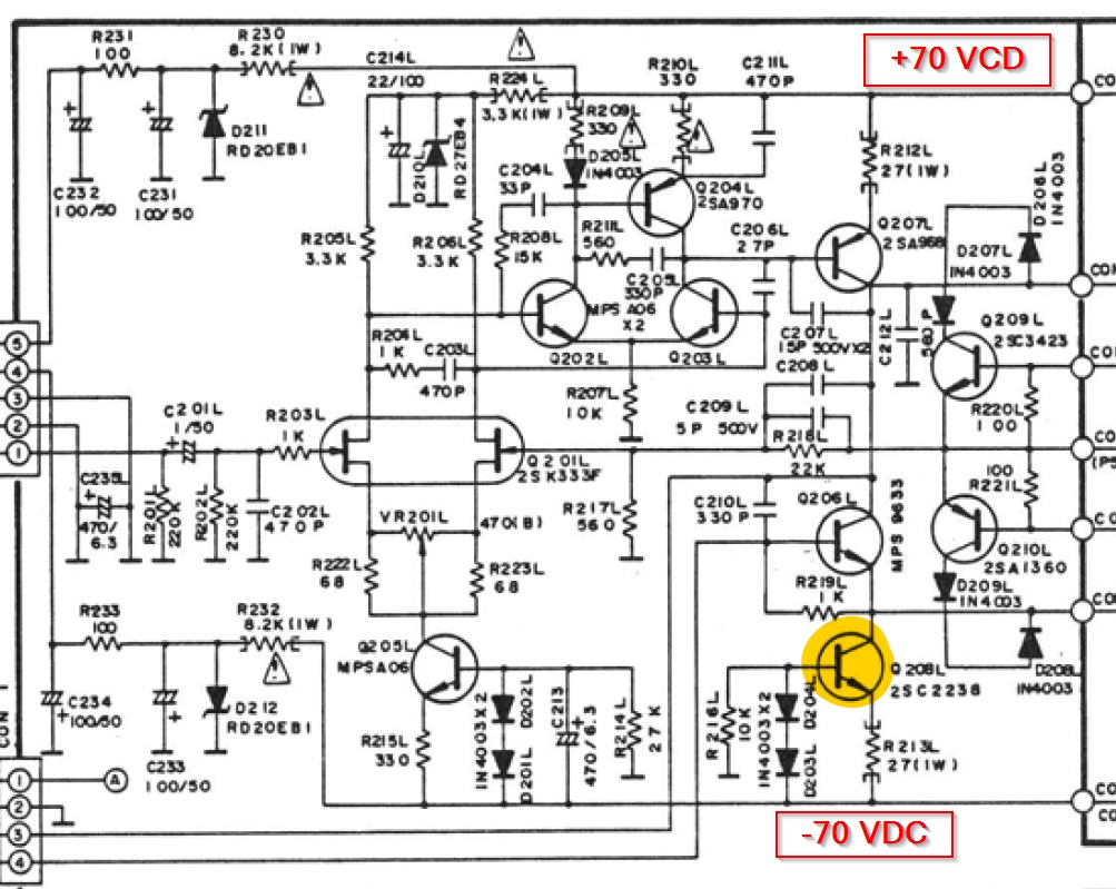
Q208, which is tied directly to the neg power rail, is running considerably warm. I pulled it and it tests fine on both a meter and on a cheap ESR meter I have. I have isolated the entire board from the two hi power channel modules. It is just floating there on its own with no outside influence and the unit will power up. I have done in-circuit comparison between channels in an attempt to locate a gross error.
I have compared the channels and found that the base on both channels is @ 71.9 vdc, the emitter is 72.5 vdc but the collector is 72.5 vdc on the normal channel and 41 vdc on the warm channel. Can someone chime in and offer some insight into the severe voltage drop?
Hello diy'ers and Happy New Year:
I picked up a 502 from a thrift shop. I always loved the aesthetics of these amps. In the 80's I used to work for Crazy Eddies, a famous NY electronics chain. The SAE line was probably the most esoteric thing they had in their (haha) sound room. Anyway, I would couple this beast with some classic Cerwin Vegas and put the U2 cd on repeat for the curious.
I even owned a brand new 502 that I bought open box when Crazy Eddie's was at its final demise. I stupidly sold it, at fire sale pricing, because I needed a car to shuffle my girlfriend around
Love make wise men blind!I open it up and smell the napalm. R243 is gone. Q241 went to the Bahamas and took C241 with him. From the tone of this thread this seems like the usual failure mode. I am really glad I came across this thread because I would have been the next fool to put a 10 ohm resistor back in, per the schematics I have.
BTW if anyone has a high res version of this schematic I would really appreciate it!
Is the final consensus to put a 1000 ohm 1/4 watt resistor at position 243?
I also plan on replacing all electrolytics as part of this repair.
There is one last issue:
Q208, which is tied directly to the neg power rail, is running considerably warm. I pulled it and it tests fine on both a meter and on a cheap ESR meter I have. I have isolated the entire board from the two hi power channel modules. It is just floating there on its own with no outside influence and the unit will power up. I have done in-circuit comparison between channels in an attempt to locate a gross error.
I have compared the channels and found that the base on both channels is @ 71.9 vdc, the emitter is 72.5 vdc but the collector is 72.5 vdc on the normal channel and 41 vdc on the warm channel. Can someone chime in and offer some insight into the severe voltage drop?
Attachments
Q208 is set to operate @ somewhere between 25mA and 30mA.
With ~68Vdc across it, it will need to dissipate ~2W.
That is mighty hot for a medium power device.
It really needs a heatsink. Preferably between 10C/W and 15C/W
The matching VAS transistor will need a similar heatsink.
Ie = {Vf(d203)+Vf(d204)-Vbeq208} / R213 = ~0.7Vf+0.7Vf-0.6Vbe / 27r = ~0.8/27 = ~0.0296A
Dissipation = ~ 68Vdc*0.0296 = 2.01W
With a normal voltage across the Vbe multiplier of around 1.3V to 2.5V, all of the remaining 140Vde has to be appled across the VAS +CCS and their resistors.
The Collector voltage on both the VAS and CCS should be close to zero volts +-1.5V
If either of these collector voltages are more than a couple of volts away from Zero volts, then something is broken.
Give me a clue. Where are Q241 and R243?
Last edited:
Q208 is set to operate @ somewhere between 25mA and 30mA.
With ~68Vdc across it, it will need to dissipate ~2W.
That is mighty hot for a medium power device.
It really needs a heatsink. Preferably between 10C/W and 15C/W
The matching VAS transistor will need a similar heatsink.
Ie = {Vf(d203)+Vf(d204)-Vbeq208} / R213 = ~0.7Vf+0.7Vf-0.6Vbe / 27r = ~0.8/27 = ~0.0296A
Dissipation = ~ 68Vdc*0.0296 = 2.01W
With a normal voltage across the Vbe multiplier of around 1.3V to 2.5V, all of the remaining 140Vde has to be appled across the VAS +CCS and their resistors.
The Collector voltage on both the VAS and CCS should be close to zero volts +-1.5V
If either of these collector voltages are more than a couple of volts away from Zero volts, then something is broken.
Give me a clue. Where are Q241 and R243?
Wow, mind blown.
Your analysis bring to mind many questions so please bear with my lack of knowledge. I have compared both the left and right channel push/pull complimentary Q207 and Q208 transistors. Are you saying that, with respect to ground, I should be seeing close to zero volts on the collectors? I was nowhere near zero on all 4. Q208 left was the only transistor that had different readings with respect to ground. Q208 left was the only transistor that was warm as well.
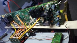
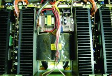
They do have 4 heatsinks on them as can be seen here:
I have been doing comparison checks between left and right channel components to look for obvious failures. I have not found anything yet. I have not been checking electrolytics though.
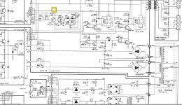
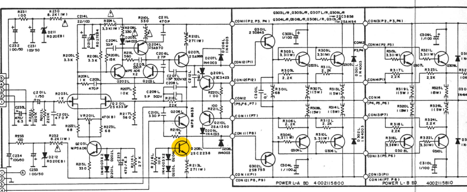
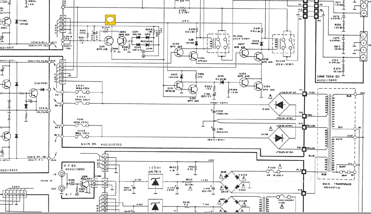
As for Q241 and R243, they are part of the protection circuitry. They can be seen here:
Pin 3 is 25 vdc unregulated. Notice the bad value for R243 of 10 ohms. I have a pretty bad 4 part scan of the schematics if you really want to see the whole picture. I would like to see if anyone on this forum has a better copy.
Attachments
I wanted to edit my previous post but alas, for some reason I do not have rights to do so. As I was driving home I kept trying to visualize what was happening with Q208. Knowing that Q208 is connected to the negative power rail wouldn't that transistor always be conducting because of how the base is configured? D203 & 204 are there for 1.4 volt drop only right? And R216 forms a voltage divider? What is the job of Q208 if there is nothing changing on the base after the mains relay closes? And for that matter if both Q207 & 208 are conducting it would appear they are shorting the plus and minus rails and putting a crazy load on R212 and R213. I am ssuming Q209 and 210 are there as a feedback loop?
I think I really want to understand this rather than just repair it. I picked this amp up to learn from it, not so much because I need another amp. I hope you fine folks can help me learn a few things.
I initially thought Q207 and 208 were pre-drivers for the main amp modules but I think I see the predriver on the amp module as complimentary 2SB755 & 2SD845 devices.
Thanks!
Attachments

Start on the right hand side of post53.
The last two boards have 4pairs of output devices.
And the driver pair are there as well.
The two IV protection are in the left board and next comes the pair of VAS+CCS transistors. Q208 is the CCS for the VAS. These two transistor form a pair that drop the majority of the 140Volts between the supply rail. Their collectors should be within a volt or tow of zero volts when no signal is present.
The 27r sets the current of the CCS. That was confirmed in my last post. And I gave you the method of calculation to predict the CCS current.
Then it has a second stage LTP using BJTs and finally the input is a jFET LTP
Your boards do not have any pre-drivers this is a double EF output stage with a 3section input stage.
Last edited:
Hi generatorlabs,
Q208 is a constant current source and is always running, so you're right about it being always turned on. The current is determined by the voltage drops from the E-B junction plus the drops across D203 and D204 across the 27 ohm resistor, R213. This current can be considered to be a constant even though it will vary a little bit with temperature and voltage changes on it's collector. Just consider the current to be a constant when you are analysing the circuit.
-Chris
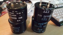
It seems as though I may have a larger unrelated problem. I wanted to completely remove the main board for easier inspection. I left the speaker connector block attached to the main board and just unscrewed it from the rear panel. That is when I observed a nice layer of oil on the previously unexposed surfaces. Where would oil come from? Well I am afraid it is not oil but electrolytic material. Now I begin to notice the light film of oil covering the plastic shrink coating of the main caps. I have never heard the amp actually play but I am sure the amount of 60 cycle hum would have been amusing. This amp has very unusual 15000uf capacitors. They are very short and are crammed into a very tight space. So I do not drag this thread in a completely different direction I am going to start a new thread on the main caps to see if anyone has found a good alternate part to fit in there. If not it looks like I may need to get a little creative. If this amp is from the 1985 era then I cannot fault the amp for having exhausted main caps after 30 years. I had the same experience with my Levinson 332 and spent a week replacing every electrolytic in that monster.
Thank you Anatech and AndrewT for your responses. As a result I know more today than I did yesterday. I see how Q208 is a constant current source as well as Q205 which services the differential amp.
I am trying to decipher what would be putting a unusual load on Q208Left but I think I should probably replace all the caps before chasing that down.
I would still like an opinion on the mislabeled R243. The schematics say 10R, others have used 5k and the last entry from user bharper states that he found a document calling for 1k. R243 can be found in the middle of this:
I hope to resume a conversation on this thread when I get main caps sourced.
Is R243 on the collector of Q241?
That looks like a speaker protection circuit.
Yes, that is correct, it is part of the safety circuits. I am dealing with two (now three) different failures. The first was the safety circuit, which is how I found this thread. The second is Q208, which was running hot. Finally the main caps along with all the other electrolytics.
I sure have picked a winner this time!
I got her breathing again! I had it on a Variable transformer dialed up to @ 70vac mains voltage for the past few hours. I did not want to stress shock the new main caps I just installed. I now have an audio source connected now and it is playing some tunes. It's like it got in a time machine and just landed here from the early 80's
I really need the alignment procedures for this amp. If anyone has those docs please PM me. I would be eternally grateful!
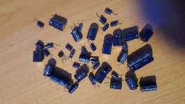
I replaced 52 capacitors, including the 2 main caps. It did not cost much money to replace all the caps but took a tremendous amount of time cross referencing and installing them. Most of the replacements are Elna Silmac-II's but there were some positions where I was forced to use equally good Nichion caps. The main caps were an a real trick to find. They are a very unusual size and there are no real direct replacements made in that configuration today. I was fortunate to find a cache of new old-stock.


Replacing a small safety circuit transistor and a resistor allowed the amp to engage the once dead output relays. I also replaced sixteen 5 watt resistors on the output devices. At some point a tech replaced one and it did not match ohms or even have the same form factor as the originals! It might have functioned but had signs of lazy, "close-enough" tech work.
These amps were hand-built and soldered. Some of the OEM soldering looked rushed. I touched it up as I went along replacing caps everywhere. A 5 watt resistor on the regulator board caused lifting & stress cracks in a trace on the PCB. I removed the conformal coating in that area and reinforced that trace with a nice bed of solder, similar to what one might see on high power traces near capacitors and power rails. The amp has no room to work easily. They used every square inch of space. I really hate that all too often I see resistors parked so close to a capacitor, even with designs that have plenty of room! This tightly packed design has some of those problems. It might be a nightmare to work on but from an engineering perspective of that era they used some really neat ideas to get that much power capacity in that small package. The transformer is particularly intriguing. It can only be described as a squished, oblong toroid.
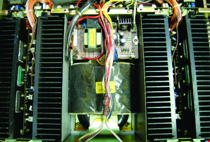
The tight space leaves little room for routing high power wires. They did not use conventional shrink tubing near 120v solder points. They just put silicone hose over the joints and used glue to keep it in place. I removed that and used double layers of shrink tube.
I am not pushing the amp hard at the moment. I am just going to let it coast along for a while as it stretches its new found legs and breaks in again. Again please, if anyone has the adjustment procedures for this amp please let me know. Thanks!
I really need the alignment procedures for this amp. If anyone has those docs please PM me. I would be eternally grateful!
I replaced 52 capacitors, including the 2 main caps. It did not cost much money to replace all the caps but took a tremendous amount of time cross referencing and installing them. Most of the replacements are Elna Silmac-II's but there were some positions where I was forced to use equally good Nichion caps. The main caps were an a real trick to find. They are a very unusual size and there are no real direct replacements made in that configuration today. I was fortunate to find a cache of new old-stock.
Replacing a small safety circuit transistor and a resistor allowed the amp to engage the once dead output relays. I also replaced sixteen 5 watt resistors on the output devices. At some point a tech replaced one and it did not match ohms or even have the same form factor as the originals! It might have functioned but had signs of lazy, "close-enough" tech work.
These amps were hand-built and soldered. Some of the OEM soldering looked rushed. I touched it up as I went along replacing caps everywhere. A 5 watt resistor on the regulator board caused lifting & stress cracks in a trace on the PCB. I removed the conformal coating in that area and reinforced that trace with a nice bed of solder, similar to what one might see on high power traces near capacitors and power rails. The amp has no room to work easily. They used every square inch of space. I really hate that all too often I see resistors parked so close to a capacitor, even with designs that have plenty of room! This tightly packed design has some of those problems. It might be a nightmare to work on but from an engineering perspective of that era they used some really neat ideas to get that much power capacity in that small package. The transformer is particularly intriguing. It can only be described as a squished, oblong toroid.
The tight space leaves little room for routing high power wires. They did not use conventional shrink tubing near 120v solder points. They just put silicone hose over the joints and used glue to keep it in place. I removed that and used double layers of shrink tube.
I am not pushing the amp hard at the moment. I am just going to let it coast along for a while as it stretches its new found legs and breaks in again. Again please, if anyone has the adjustment procedures for this amp please let me know. Thanks!
Attachments
- Status
- This old topic is closed. If you want to reopen this topic, contact a moderator using the "Report Post" button.
- Home
- Amplifiers
- Solid State
- SAE A502 Keeps smoking protection transistors