Attachments
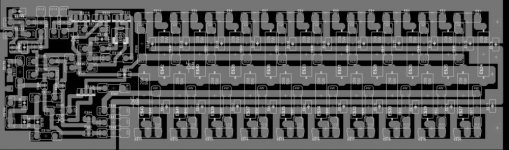
Looks like a little better layout - 2 sided boards help a lot. But if the speaker output is the yellow wire, it's at the wrong end. The speaker out and the feedback tap need to come off the same end of the emitter resistor bus. Preferably, Bus-->Spk-->FB. Otherwise, a distorted signal can end up being fed back.
For those considering high power class AB:
This amount of power is not practical in plain class AB. Far more power is wasted as heat than delivered to the speaker when playing music. The power supply and cooling requirements become a bit insane, like the number of pairs of output devices. You would end up expending far more money in such a DIY stone-age design than in buying a commercial amplifier.
Consider getting a class H QSC clone, like Behringer EP2500. You can reverse engineer it and learn class H btw.
Another alternative is class D, but ready made high power designs are not available for DIY and you would probably expend a few years learning how to do it properly (like I did).
wg_ski said:Looks like a little better layout - 2 sided boards help a lot. But if the speaker output is the yellow wire, it's at the wrong end.
Actualy the speaker wire is at the correct end - the speaker current flows parallel and in the opposite direction to the supply rail current.
The nfb pick-off is at the wrong end. A length of shielded cable for the nfb pick-off, running from the far end of the board with the shield connected only at one end (to the signal ground) works for me.
A length of shielded cable for the nfb pick-off, running from the far end of the board with the shield connected only at one end (to the signal ground) works for me.
OMG , This is acceptable??... I do this on my new amps (supersym), but wasn't sure it was an acceptable practice.
In theory , it should be more ideal than the NFB trace snaking around within the circuit.
")
OS
ostripper said:
OMG , This is acceptable??... I do this on my new amps (supersym), but wasn't sure it was an acceptable practice.
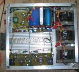
Been there done that bought the T-shirt. See that pair of wires crossing over the middle of the heat sink? One of those is the NFB and signal ground. The other is a "dirty" ground - brought back to the caps individually, of course.
Not only does it result in an order of magnitude lower distortion compared to running a bare wire, but it prevents hum from being induced in the NFB from the amplifier above it in the rack. This was a problem.
Now it would be way better on all accounts to just have a cleaner layout. But many times with these type amps, physical construction and using what's on hand dictate how it goes together.
Attachments
Now it would be way better on all accounts to just have a cleaner layout.
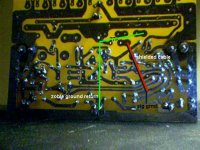
The cable is what allowed the "cleaner layout". I did all the "dirty work" under the board (attached). Did the same with the zoble.
In the end , no hum , no problems.
BTW - WG ,what amp is that?
OS
Attachments
hi danieljw,
You have attached Jean Hiraga Super class A amp; it is very interesting for me
I don't know if this is the place to chat about it but I will be very glad if you can help with some questions, I am waiting for your approval to start the questions
You can email direct to me or tru the forum
Best regards
Williams
can you give us more detail on this NFB/Signal Ground link and how not to do it.wg_ski said:One of those is the NFB and signal ground...............................
....................Not only does it result in an order of magnitude lower distortion compared to running a bare wire, but it prevents hum from being induced in the NFB
- Status
- This old topic is closed. If you want to reopen this topic, contact a moderator using the "Report Post" button.
- Home
- Amplifiers
- Solid State
- 1500 Watt