I have already registered this in the thread Dummy Load, but from that i see up to moment, it passes unnoticed. Because it is something very important for all that from us engaged with self made amplifiers, i took the courage to post him as a separate thread because he is absolutely different from all the other dummy loads that presented in the old thread. I hope to you not misunderstand this.
I wanted therefore to make, as all, a dummy load with certain advantages as:
1. It is clearly ohmic and it does not appears inductive resistance
2. It withstands in very large amounts of power dissipated
3. Does not exist danger of personal accident from his heating during test procedures
4. It can become easily 4Ù or 8Ù without time-consuming processes.
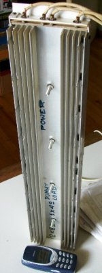
Thus, and after a lot of search, i led to this construction that appears in the photo, as it was the more practice and inexpensive. Her parts are the following: 1) One inexpensive heat sink of one metre length 2) A foil of micalite who is used in electric irons. 3) Certain metres nickel - chromium edge wound ribbon that it used in the manufacture of electric resistances for heaters. The two last materials you can find in any workshop it repairs electric resistances for domestic appliances. In Thessalonica at Greece, i found at least 4 such workshops. Make a visit in a workshop of your region, you will find there also a lot of high current materials that are usually not sold in electronic shops. What you see in photo, it is a sandwich between the two halves of heatsink, in that are pressed two separate resistances of 8Ù each. They do not present induction because every one is only turned two times – the length of sandwich is 0,5 m – and have a core diameter of zero as you can easily understand. The power of each resistor is incredibly high and exceeds 2,5KW. If connected in parallel between them, you have immediately a dummy load of 4Ù. Due to big size of heatsink, the temperature does not exceed in either case the 50°C. Thus is provided safety from accident but simultaneously the resistance has negligible inclination from her nominal value when it is heated. I have made tests for this with professional amplifiers of 1200Wrms and i can confirm this. In any case even if the temperature goes up in 100° C the inclination of resistance is +0,16Ù from her nominal value. In order to it is constructed, of course they need some machination, and because i have the parts to construct a second unit i thought that it is better of making a new construction from the zero with photos and instructions step by step, so that to understand him all. Make therefore patience for certain days, i promise to begin from tomorrow the construction and at the end of next week i have presented him.
I wanted therefore to make, as all, a dummy load with certain advantages as:
1. It is clearly ohmic and it does not appears inductive resistance
2. It withstands in very large amounts of power dissipated
3. Does not exist danger of personal accident from his heating during test procedures
4. It can become easily 4Ù or 8Ù without time-consuming processes.
Thus, and after a lot of search, i led to this construction that appears in the photo, as it was the more practice and inexpensive. Her parts are the following: 1) One inexpensive heat sink of one metre length 2) A foil of micalite who is used in electric irons. 3) Certain metres nickel - chromium edge wound ribbon that it used in the manufacture of electric resistances for heaters. The two last materials you can find in any workshop it repairs electric resistances for domestic appliances. In Thessalonica at Greece, i found at least 4 such workshops. Make a visit in a workshop of your region, you will find there also a lot of high current materials that are usually not sold in electronic shops. What you see in photo, it is a sandwich between the two halves of heatsink, in that are pressed two separate resistances of 8Ù each. They do not present induction because every one is only turned two times – the length of sandwich is 0,5 m – and have a core diameter of zero as you can easily understand. The power of each resistor is incredibly high and exceeds 2,5KW. If connected in parallel between them, you have immediately a dummy load of 4Ù. Due to big size of heatsink, the temperature does not exceed in either case the 50°C. Thus is provided safety from accident but simultaneously the resistance has negligible inclination from her nominal value when it is heated. I have made tests for this with professional amplifiers of 1200Wrms and i can confirm this. In any case even if the temperature goes up in 100° C the inclination of resistance is +0,16Ù from her nominal value. In order to it is constructed, of course they need some machination, and because i have the parts to construct a second unit i thought that it is better of making a new construction from the zero with photos and instructions step by step, so that to understand him all. Make therefore patience for certain days, i promise to begin from tomorrow the construction and at the end of next week i have presented him.
Attachments
gni said:Here in the United States:
A 900 watt heater coil that runs on 120 volts AC would result
in a resistive load of 16 ohms; paralled would be 8 ohms, and four
units would be 4 ohms. . . now you got me thinking.
... but that is only when it actually dissipates 900 W. If less, the resistance would be MUCH lower. This kind of stuff is unusable for amp loads.
Jan Didden
Be careful, because the coil heaters, contain a resistor wire that is turned arround a ceramic rod. Thus they present a notable inductance and his load is not clear ohmic as needed.gni said:Here in the United States:
A 900 watt heater coil that runs on 120 volts AC would result
in a resistive load of 16 ohms; paralled would be 8 ohms, and four
units would be 4 ohms. . . now you got me thinking.
http://www.farnell.com/datasheets/41655.pdf
http://www.farnell.com/datasheets/814.pdf
http://www.farnell.com/datasheets/34452.pdf
BUT resistive loads do not allow checking for back-EMF induced class-AB crossover error, unless they are used to generate the reference potential when two identical channels are being driven by the same source -
ie. monitor the difference in outputs between linear/resitive loading and approximate R-L-C dynamic loading.
And don't forget, as Graham Maynard says, that the clear ohmic (resistive) load offered primarily for the measurement of the power output. In the cases, when we want to see the transient reactions of the amplifier, a MKT capacitor or a inductor should be connected in parallel with the dummy load at the output of the amplifier to simulate a complex load such a speaker.
- Status
- This old topic is closed. If you want to reopen this topic, contact a moderator using the "Report Post" button.