I would like to start by saying hello to everyone at this awesome site. I just found it about a month ago and am hooked. There are some very talented and amazing people here and I am glad I can be a part of it.
I have been looking around here almost every day and finally decided to make the plunge and just build something. I have spent hours pouring over articles and threads in the Pass Labs section. I love the designs of Nelson's amps and was dead set that my first amp was going to be some variation of the Zen. The a couple days ago I decided to start with something a little bit easier and with something I already had all the parts for. I looked though some of my collection of articles and decided I would build a 1969 JLH with a few changes. So I spent a couple days rummaging through all my stuff and all my dad's stuff, scraping together parts as I went. Last night as I was breadboarding it I decided to just go ahead and P2P solder it. I finished it at about 7:00, hooked everything up, then got hungry So I got some dinner, lol. Anyways I came back later, hooked my iPod into it, and success! I was amazed, it actually worked! I usually listen to music through either a inexpensive Sony all-in-one theater system or a Knight KN940, I must say that the JLH sounds amazing. The knight still sounds good (it uses 12AX7's for preamp's and 6BQ5's for power tubes), but it is old and not in the same class as the JLH (as far as I know, I think it is a class AB push pull). The knight also has some noise, tube hiss, and I think the electrolytic caps are getting old; also the 12AX7's make some really crazy micro-phonic (I think the correct term) when they even get slightly bumped. The quality of the Sony doesn't even compare, not by a long shot. I hear stuff with one mono that I couldn't hear with the Sony. There are more sounds being reproduced, and there is much more depth than I experienced with the Sony or the Knight. The sound is also, I guess more defined. I can hear separation in the notes of a piano or between the chords of a guitar. The biggest difference I have noticed is in the drums. I listed to Blue Man Group, just for the hell of it, and it was like going on a trippy sonic journey (sorry, college kid, you know how we are), there was a whole new depth to the sound. There was a nice snappy bass, individual and distinct snares, and you could hear the individual hits of their wacky drum-like instruments. Maybe I am partial to it because it is my first high-fi class A amp I have built and heard, but I love it.
I do however have some questions about it.
1. Is it possible to add more pairs of output transistors to the output end? Would running 2 or 3 pairs give you any advantage over just running a single pair? I know it is better most of the time in Class A to keep it simple and single ended, but I am curious.
2. How critical are the values of the caps? I am mostly talking about C1,C2, and C3. I have heard changing the values changes the sound, that 470uF is actually a good capacitance for C1 and C3. Is this just something I can fiddle with and see what sounds best to me, or are the fairly critical? Also what would have to be done to rid of C2 (the output cap), or would changing it be better? I have read they sound better with out it, can the value of it be fiddled with also?
3. I am looking for suggestions for Q4 and Q3. Right now I am running a 2N3906 in the Q4 position and, I hate to say it, a 2N2222 in the Q3 position. I wanted to get the amp working and I didn't have any 2N1711's or anything. Could I have used a 2N3904, because I do have one of those left. I am sure the 2222 has some effect on the sound that is adverse. I was thinking of replacing them with 2SA1358 (Q4) and 2SC3421 (Q3). I think this would work, but I am just looking for an expert opinion.
4. Does giving the JLH lots of capacitance on the PSU side effect the sound a lot or not. The supply I am building for the final setup will have a single 47,000uF cap per JLH, should I go higher. I had considered getting a pair of 68,000uF caps instead. I could also get a pair of those per rail, giving me 138,000uF per JLH, which seems like an awful lot.
5. Does regulating the PSU give it any better sound? I know I have read that regulating Gain-Clones gives them better sound and tighter control, but this a different animal.
I am currently running 3055 which I plan on upgrading after I get the full amp constructed and housed in its case. Hopefully I can get pics soon, I have a really crappy digital cam. Maybe I will post some, then in a week and a half when my girlfriend is home I can use here good camera. Thanks to everyone here again for this amazing wealth of info. Also thanks to anyone who bears with me through this learning process and this brutally long post") .
.
PS: I did search a bit for some of the questions and found some stuff. I am still in the process of searching and play with the amp, so if the questions have be asked before just call be dumb and tell me to search again,lol.
I have been looking around here almost every day and finally decided to make the plunge and just build something. I have spent hours pouring over articles and threads in the Pass Labs section. I love the designs of Nelson's amps and was dead set that my first amp was going to be some variation of the Zen. The a couple days ago I decided to start with something a little bit easier and with something I already had all the parts for. I looked though some of my collection of articles and decided I would build a 1969 JLH with a few changes. So I spent a couple days rummaging through all my stuff and all my dad's stuff, scraping together parts as I went. Last night as I was breadboarding it I decided to just go ahead and P2P solder it. I finished it at about 7:00, hooked everything up, then got hungry So I got some dinner, lol. Anyways I came back later, hooked my iPod into it, and success! I was amazed, it actually worked! I usually listen to music through either a inexpensive Sony all-in-one theater system or a Knight KN940, I must say that the JLH sounds amazing. The knight still sounds good (it uses 12AX7's for preamp's and 6BQ5's for power tubes), but it is old and not in the same class as the JLH (as far as I know, I think it is a class AB push pull). The knight also has some noise, tube hiss, and I think the electrolytic caps are getting old; also the 12AX7's make some really crazy micro-phonic (I think the correct term) when they even get slightly bumped. The quality of the Sony doesn't even compare, not by a long shot. I hear stuff with one mono that I couldn't hear with the Sony. There are more sounds being reproduced, and there is much more depth than I experienced with the Sony or the Knight. The sound is also, I guess more defined. I can hear separation in the notes of a piano or between the chords of a guitar. The biggest difference I have noticed is in the drums. I listed to Blue Man Group, just for the hell of it, and it was like going on a trippy sonic journey (sorry, college kid, you know how we are), there was a whole new depth to the sound. There was a nice snappy bass, individual and distinct snares, and you could hear the individual hits of their wacky drum-like instruments. Maybe I am partial to it because it is my first high-fi class A amp I have built and heard, but I love it.
I do however have some questions about it.
1. Is it possible to add more pairs of output transistors to the output end? Would running 2 or 3 pairs give you any advantage over just running a single pair? I know it is better most of the time in Class A to keep it simple and single ended, but I am curious.
2. How critical are the values of the caps? I am mostly talking about C1,C2, and C3. I have heard changing the values changes the sound, that 470uF is actually a good capacitance for C1 and C3. Is this just something I can fiddle with and see what sounds best to me, or are the fairly critical? Also what would have to be done to rid of C2 (the output cap), or would changing it be better? I have read they sound better with out it, can the value of it be fiddled with also?
3. I am looking for suggestions for Q4 and Q3. Right now I am running a 2N3906 in the Q4 position and, I hate to say it, a 2N2222 in the Q3 position. I wanted to get the amp working and I didn't have any 2N1711's or anything. Could I have used a 2N3904, because I do have one of those left. I am sure the 2222 has some effect on the sound that is adverse. I was thinking of replacing them with 2SA1358 (Q4) and 2SC3421 (Q3). I think this would work, but I am just looking for an expert opinion.
4. Does giving the JLH lots of capacitance on the PSU side effect the sound a lot or not. The supply I am building for the final setup will have a single 47,000uF cap per JLH, should I go higher. I had considered getting a pair of 68,000uF caps instead. I could also get a pair of those per rail, giving me 138,000uF per JLH, which seems like an awful lot.
5. Does regulating the PSU give it any better sound? I know I have read that regulating Gain-Clones gives them better sound and tighter control, but this a different animal.
I am currently running 3055 which I plan on upgrading after I get the full amp constructed and housed in its case. Hopefully I can get pics soon, I have a really crappy digital cam. Maybe I will post some, then in a week and a half when my girlfriend is home I can use here good camera. Thanks to everyone here again for this amazing wealth of info. Also thanks to anyone who bears with me through this learning process and this brutally long post
.PS: I did search a bit for some of the questions and found some stuff. I am still in the process of searching and play with the amp, so if the questions have be asked before just call be dumb and tell me to search again,lol.
Here are some crappy pictures of my current JLH semi test setup and other stuff:
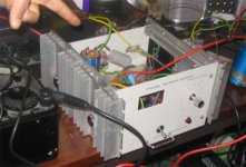
This is the JLH up close and personal:
http://i173.photobucket.com/albums/w48/JPeitzman/MVC-010F.jpg
Here is the amp as a whole, the PSU is a bench setup a built a while ago. Only one side of it is currently working. It puts out about 28.5 unregulated volts, nothing special.
http://i173.photobucket.com/albums/w48/JPeitzman/MVC-012F.jpg
Here is a close up of the old school RCA 3055's. They are brand new, but are still about 25 years old, just never used. They along with about 30 others are sitting in a draw waiting for a home.
http://i173.photobucket.com/albums/w48/JPeitzman/MVC-011F.jpg
Here is one of the so so Fisher speakers that it is playing through with my iPod on top. I intend to build way nicer speakers in the summer.
http://i173.photobucket.com/albums/w48/JPeitzman/MVC-013F.jpg
Here is the PCB that will hold most of the finalized amp. It is going so so, but the board is a bit small. I know the picture is really bad, sorry.
http://i173.photobucket.com/albums/w48/JPeitzman/MVC-015F.jpg
This is one of the heatsinks that will make the sides of final case. I have about 12 of these, they are beautiful once they get cleaned up.
http://i173.photobucket.com/albums/w48/JPeitzman/MVC-016F.jpg
Finally here is a picture of my KN940. For being not the highest quality it has served me very well.
http://i173.photobucket.com/albums/w48/JPeitzman/MVC-014F.jpg
So there you have it so far.
Thank you very much for your comment Mr. Pass, it means a lot coming from you.
One more quick question, can I use Darlington's on the output side? Or would this mean that I would have to change the circuit? On the new boards I am using 2N3904's for Q3 until I can get something better.
Thanks again to all.
Hi
Congratulations on your first posts to diyaudio.
Try this site which contains all the collected writings of JLH
http://www.tcaas.btinternet.co.uk/
I think most if not all of your questions are answered there.
I also built the original and newer JLH designs some years ago and I am a fan. If you check the above site you will find articles and designs with single ended and balanced power supplies and also more output transistors. There is also an updated jlh design on diyaudio by Graham Maynard for the Gem Class A amplifier which is in effect an update/improvement of the JLH design (my words not Grahams ).
Don
Thanks for the site, it is loaded with info!
Have you noticed much audible difference between the new and old designs? The new one besides having split rails also has a constant current source too right? I have though about modifying my design to have a CCS, I just didn't know if it would make much of a difference. I have thought about trying the split rail design too, just to get rid of the output cap. I also saw the high power version, I kind of like it too, but do you need the CCS on the signal slitting transistor do you think?
I have been working (well late into last night at least) on a couple different designs. I am trying to figure out if I can use a long tailed pair in conjunction with the signal splitting design. Mostly because I am also trying to lay out a amp design of my own and have though about this method.
I do think though that once the final 1969 JLH gets put together I will try a high power version. That way I can just buy 12 MJ15003's and replace all the 2N3055's in the original as well. I think I might try some Darlington's that I have as well, unless anyone thinks they will not work. I have a box or two of them just sitting around. My dad has a 2000+ square foot shop that has been collecting electronic junk for 30 years. He also worked for RCA and serviced theater systems, hence the use of RCA 3055's. I am thinking too about a tube amp, since we have 3 big boxes of tubes from theaters, one with about 12 807's.
Thanks for the info!
Hi
I will try to answer some of your questions although there are others on this site more knowledgeable than myself.
There is a difference in sound between the original and newer design although I do not think it is that great. The main diference with the later split rail design is the elimination of the output capacitor. However I find that if you use a top quality capacitor with film bypass capacitors on the original design that sounds excellant.
My findings are that changing the transistors made the biggest difference in sound. My versions use MJ15003/4 output capacitors which you are changing to. There are notes on the web page I gave you about using more modern transistors essentially saying that some are too fast and can cause problems. My version of the later dersign uses two output transistors per rail and operates at +/-30 volts with 2 amp current. I use a higher current as my speakers are 3.8ohm and need a higher current to drive them.
The web page also contains notes I believe from JLH about using a constant current source. Some folks think they sound better others prefer the sound of the simpler resistor solution. You will also find some discussion on the use of resistors or constant current sources on the Pass web sites and threads on diyaudio. Generally the consensus seems to be that you have to try a resistor and various types of constant current source to decide which gives the best sound. If it helps you I find a resistor sounds best in the original design but I prefer a constant current source in the later design.
You mention a tube amp. If you look at the original JLH circuit you will see that it is designed along the same principles as a tube amp. It does have a very tube like sound.
I think you may find the Pass web site and Passdiy site of interest. Nelson Pass is very generous and provides a lot of info on his designs and the web sites are also full of articles on the sort of subjects you seem to be interested in.
Don
Thanks for the comments guys! Here are some new pics after a little bit of work.
Here is the first of the heatsinks mounted on a temporary case I made last night in like 5 min.
http://i173.photobucket.com/albums/w48/JPeitzman/sink.jpg
Here is the first of the boards I soldered up on a small prototyping board. It works wonderfully but I am not as happy as I thought with the look. I am going to etch a PCB I think instead, unless anyone knows where I can buy some PCB's for a good price in the stated for the JLH.
http://i173.photobucket.com/albums/w48/JPeitzman/amp.jpg
Hi JPietzman
There has been much comment about the JLH69 in the JLH class A thread. I guess you have read this by now? I've posted a circuit using MJL3281A's in the output.
I too built my first JLH with RCA 2N3055's. I was disappointed with the sound - and Graham Maynard has also written similar account.
At low powers, the 69 Class A sounds pretty good, but at higher powers when the current excursions get rather large, the slew rate is somewhat limited by the frequency response of the 3055.
I got some improvement with the latest epi 2N3055's and have mostly used ST 2N3055, but the ON Semi 2N3055 has a SOA which is closer to the original RCA 2N3055. But the simulation with the MJL3281A's just blows all these away. 200 MHz, no slew limit apparently.
But as Carlos might say - it all depends on how critical your listening experience is.
cheers
John
JLH Manhatten style
Greetings everyone. I thought I would share my experience of the JLH 1969 I recently built. Build manhatten island style on a single sided board, with small islands of double sided soldered in place. Took less than an hour. Worked first time. Toshiba 2n3055s sound nice, but would love to hear if the MF15003s would really make significant improvement. Am going to try a GEM next for my son, who needs more power!.
This is what it looks like..
Rich
Attachments
Hi Rich
My guess is that the Toshiba 3055 is an epi base too. (You have got real Toshiba 3055's I hope?) If so then I suspect these would sound fine. Not much problem as long as the quiescent current is turned up enough to counter the gain roll-off, as has been mentioned earlier, but I don't know whether Toshiba make these more linear than the old devices.
I'm not sure why the MJ15003's would be much different - these are also epi base with ft's around 2-3 MHz.
good to hear that the circuit is still liked by you, Jpietzman and others!
cheers
John
Thanks for the responses guys! I have my board setup so that i can easily change all the transistors. I made little sockets to I can plug in any 3 lead package or I can plug in a pair of TO-3 sockets like I have now. I might have to play a little with output devices. I sent in order into Mouser on Thursday for some BC560's and 2N3019 to replace my 2N3906 and the ill-fitted 2N2222 that I think is degrading the sound. I think in the next week or so I might order up some MJ15003's and see how they sound. I have some Darlington's I was thinking of trying but haven't for the fact that I am almost sure they won't work right.
I am also going to be trying my hand at some etching soon, which with some luck should go good. I am planing on making boards for the JLH, a dual rail JLH that uses CCS's, and maybe a LTP Zen (thanks Allen Newby for that one) or an Aleph Mini. I have a lot of projects slated and unfortunately not many are getting done. I am planing on finishing part of our basement for a theater, so I need to frame, insulate, drywall, paint, and all that junk. Plus for this project I am building my own amps and speakers, I just don't know what amps to use. I am building a small system for my computer that has been drawn out but not started. I am also building a small 2 or 2.1 channel system for my room that also hasn't been started yet. I am laying out a amp design of my own, which is actually going very good, seeing as how I am learning as I go. Plus I want to build just about everything I find here which is turning into a problem, lol.
I second half of the JLH is mostly finished, I hit a snag this weekend. I had planned on finishing it and taking some pics, but this was my weekend to see my girlfriend, so it didn't work out. I live back home and goto school, and she goes to the University of Iowa, about an hour away, it sucks. Dating for almost 4 years and now we get to see each other twice a month and during the summer. Thank god I found this site loaded with projects to keep me busy! I had her listen to some music on the JLH and she loved it. In fact she actually preferred it over my tube amp by a lot.
Anyways that is the update so far. Soon I will be getting some PCB's, some new resistors, some nice Elna Cerafine's, and some nice new output transistors. This summer some cases will be built when I have more time.
I would like to ask though; I am planing on getting some IRC or Vishay resistors, should I instead try to source some Halco's, or should Vishay's be fine? I am planing on going for ½watt 1%'s for all the resistors except for any that need to be rated higher.
Thanks again for the feedback, links, suggestions, everything! Hopefully I can get the test JLH finished by the end of the week with some new pictures. I am hoping too that by then I can finish a preamp, and maybe do a little etching.
John,
The 2n3055s are genuine Toshiba. With 1.2 amps the heatsinks sit at just under 50 degC so all seems happy. There was someone talking about huge power supply caps - I have 33,000 uF and that is probably excessive.
JP in Iowa,
I wouldn't bother doing pcb etching with such a simple and low part circuit. This is my effort, both channels and it looks OK doesn't it?
The board is at ground and soldered to it are bits of double sided pcb for parts. Couldn't be easier. The heavy wiring is for the high current parts.
www.sweetpeas.pwp.blueyonder.co.uk/JLH-interior.jpg
Apologies for the dissimilar .47nF inputs and the 2500uF outputs but I can't hear any difference in either channel's sound!
Rich
- Status
- This old topic is closed. If you want to reopen this topic, contact a moderator using the "Report Post" button.
- Home
- Amplifiers
- Solid State
- The first half of my 69JLH works!!