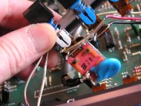
Here is the photo of the Alps TV-5 switch from this unit. It does not power up and I suspected the switch. When I depress the on button (not plugged in), shouldn't I get continuity across the incoming power (black leads near the ceramic cap)? Also, why is it that I'm reading an open circuit across the red and both white and black leads when the button is depressed (unit on) and continuity when the button is not depressed (unit off)?
Attachments
Hi DreadPirate,
I'd have to look at the manual to answer your questions. But I have to ask, if you don't know what you are doing, why are you doing it???")
That switch is unobtainium. Micron Electronics in Mississauga Ontario may possibly have one. Be prepared to pay for it if you need a switch.
That blue thingy is supposed to stop the contacts from arcing. The front part of the switch operates the muting circuit (from memory). What you need to do is troubleshoot it logically. The big part is 120 VAC, the front part is low voltage. Don't shock yourself.
-Chris
I'd have to look at the manual to answer your questions. But I have to ask, if you don't know what you are doing, why are you doing it???
That switch is unobtainium. Micron Electronics in Mississauga Ontario may possibly have one. Be prepared to pay for it if you need a switch.
That blue thingy is supposed to stop the contacts from arcing. The front part of the switch operates the muting circuit (from memory). What you need to do is troubleshoot it logically. The big part is 120 VAC, the front part is low voltage. Don't shock yourself.
-Chris
The form factor does not appear to correspond to any in the current ALPS literature. Could I just ignore the front end part and replace with an A/C switch? It seems to work fine. I'm still missing how I'm not getting continuity between the two black leads, isn't the switches function to make or break the connection between the black leads?
I understand what you're saying about obtaining primary coil resistance across the power connector, but I read open with or without the switch in the "on" position. The two black wires on the power switch may activate the "switched" outlets on the rear of the unit. When I plug the unit in, I strangely get 6.6V on the "switched" outlets and 110V on the unswitched. When I activate the power switch, the "switched" outlets go to 110V and the unit turns on. Tracing those wires back, they see line voltage (110V).
I can't explain why, but by disconnecting the red and white wires (shown on the photo) from the switch, I can get the unit to turn on and off normally. When they were connected, the unit would not power on at all.
Maybe I should get ahold of the schematic?
I can't explain why, but by disconnecting the red and white wires (shown on the photo) from the switch, I can get the unit to turn on and off normally. When they were connected, the unit would not power on at all.
Maybe I should get ahold of the schematic?
Hi DreadPirate,
I wish I still had my manuals, I'd be able to tell you.
-Chris
Yup.Maybe I should get ahold of the schematic?
I wish I still had my manuals, I'd be able to tell you.
-Chris
hi..these switches have double contacts ..the nubs on the opposite side ... are still useable ..just solder to the unused 2 contacts and you have a new switch!
zeenith@msn.com
denis
zeenith@msn.com
denis
- Status
- This old topic is closed. If you want to reopen this topic, contact a moderator using the "Report Post" button.
- Home
- Amplifiers
- Solid State
- Carver C-1 Preamp Power Switch