Hi
I read Reviews about IGBTs, MosFETs and BJTs uses in Audio Power amplifiers.
I want to build the Elektor 50W Compact AF IGBT power amplifier. I want to replace IGBTs with BJTs.
I have two questions:
1- which components should I change?
2- What is the best BJT to use? (part Number)
P.S. I know how to replace it with MosFET. But I do not know about BJT replacement.
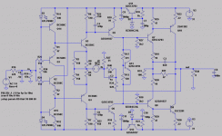
Here is the Original Design.
http://www.4shared.com/file/10820796/362d5b1f/CompactIGBTPowerAmp.html
Here another design with BJT from the same designer. maybe it could help. (I don't know the supply Voltages)
http://www.4shared.com/file/10820833/b7f40027/ne5534pa.html
ThanX
Shahriar
Hi Shahriar,
Just change the collector resistors of MJE drivers from 390ohms to 68 ohms and igbt gate resistors from 22 ohms to 4.7 ohms 1W for BJT bases , Also insert 100 ohm resistors inthe bases of MJE drivers and readjust the bias for Iq=100mA for output BJT's
Also change the emitter resistors of output BJTs to 0.47ohm 5W non-inductive types
For BJTs You can use 2SC5200/2SA1943, MJ21195/MJ21196, MJ15003/MJ15004, MJ15024/MJ15025, TIP35/TIP36
Caution: These type of Geisberts designs were prone to oscillations, try to check this amp for stability also
regards,
K a n w a r
Hi
ThanK you very much for your reply.
I have also found this design very close to Accuphase Power Amp.
I have attached a link which is a manual for Accuphase and another schematic which is related to some one who has tried to draw a schematic from a hardware. (it has some mistakes)
http://www.4shared.com/file/10268547/66af6ce3/Accuphase_px-600e.html
http://www.4shared.com/file/9862517/f6dea3bb/AmirHosseinAccuphase.html
What if we try to put the output section as Accuphase has done. Just remove the parts after Variable Zener in Elektor design and replace them with topology in Manual block diagram (figure 2)
ThanX
Shahriar
Shahriar said:Thnk you your reply.
But damping factor for this Elektor IGBT PA is 700 (1KHz)
For Accuphase p-650-e Model with 4 Emitter output is 270.
Shahriar
These Damping Factor Figures are obtained by the virtue of amount of applied negative feedback
while I was stating in case of open loop amp or simply a buffer with out any feedback
Shahriar,
been there, done that. All I can say is, don't it. Using 2SA1943/2SC5200 as output devices with the attached schematic, the sound became really dark. Although it measured fine on the bench, I frankly though that the tweeters in my Proac Studios were busted. I tweaked the design for loop gain/feedback and waited for the bjt's to break in, but the character of the sound never changed. I switched back to the igbt's and sonic happiness is here again. These high frequencies are waaaayyyyy better that they have ever been with the bjts. And no prejudice here.
been there, done that. All I can say is, don't it. Using 2SA1943/2SC5200 as output devices with the attached schematic, the sound became really dark. Although it measured fine on the bench, I frankly though that the tweeters in my Proac Studios were busted. I tweaked the design for loop gain/feedback and waited for the bjt's to break in, but the character of the sound never changed. I switched back to the igbt's and sonic happiness is here again. These high frequencies are waaaayyyyy better that they have ever been with the bjts. And no prejudice here.
Attachments
- Status
- This old topic is closed. If you want to reopen this topic, contact a moderator using the "Report Post" button.
- Home
- Amplifiers
- Solid State
- Replacing IGBTs with BJTs in Elektor IGBT design!
