No, it will never start to sound bad, no matter how much you add on. You could out on Farads and Farads if you like.  Of course as the caps are charging (as you power up your amp), they draw a very high current from your trannie, and will do so longer as the caps get bigger. Then there's the cost thing.
Of course as the caps are charging (as you power up your amp), they draw a very high current from your trannie, and will do so longer as the caps get bigger. Then there's the cost thing.First question: How big is your room?Christian said:Is there a limit on how much caps you should use with your x-former. I mean, does it beginn to sound bad if you use too many caps on a small x-former?
/Chris
That will set a limit to how many Caps you can Fit.
Second Question: Is there a part of the kitchen you could use?
That can add some 10 Farad.
I am just guessing, but is it a Pass Amp you are going to supply?
Then you might even better use your Garage, too ...
Put your Car on your lawn instead.
/halojoy - with his Caps on
Adding Caps to Powersupply
According to Horowitz this a is totally <B>NOT</B> true. "When choosing filter capacitors, don't get carried away: An oversize capacitor not only wastes space but also increases transformer heating (by reducing the conduction angle, hence increasing the ratio Irms/Iavg). It also increases stress on the rectifiers"
Better use a PI-filter. This will reduce the ripple far more effectively. You can make the second cap larger at will.
See also
http://db.audioasylum.com/cgi/m.pl?...light=elso+capacitor+power+supply&r=&session=
Hi Kilowatt,Kilowatt said:No, it will never start to sound bad, no matter how much you add on. You could out on Farads and Farads if you like.
According to Horowitz this a is totally <B>NOT</B> true. "When choosing filter capacitors, don't get carried away: An oversize capacitor not only wastes space but also increases transformer heating (by reducing the conduction angle, hence increasing the ratio Irms/Iavg). It also increases stress on the rectifiers"
Better use a PI-filter. This will reduce the ripple far more effectively. You can make the second cap larger at will.
See also
http://db.audioasylum.com/cgi/m.pl?...light=elso+capacitor+power+supply&r=&session=
I'd have trouble believing that, because through the rectifier, I don't see how the transformer could possibly care if there are huge charged caps beyond it. But then again, I'm far from all-knowing.
And besides that, audiophiles aren't normally known to care about such things as efficiency.
But then again, I'm far from all-knowing. And besides that, audiophiles aren't normally known to care about such things as efficiency.
Soundquality
As for soundquality a PI-filter with 2x 10,000µF and a 2.2 mH choke sounded better than the simple powersupply with doubled capacity. (2x 10,000µF)
I tried this in my own poweramp (AmpzillaII)
Hi Klowatt,Kilowatt said:I'd have trouble believing that, because through the rectifier, I don't see how the transformer could possibly care if there are huge charged caps beyond it.
And besides that, audiophiles aren't normally known to care about such things as efficiency.
As for soundquality a PI-filter with 2x 10,000µF and a 2.2 mH choke sounded better than the simple powersupply with doubled capacity. (2x 10,000µF)
I tried this in my own poweramp (AmpzillaII)
Re: Re: Capacitance Limit?
I love the (mental) picture: the room kitchen and garage full of those large beercansize caps!
I think the transformer will not survive the first inrush current charging those 10kF capacity. maybe I forgot a zero!
Hi Halojoy,halojoy said:
First question: How big is your room?
That will set a limit to how many Caps you can Fit.
Second Question: Is there a part of the kitchen you could use?
That can add some 10 Farad.
I am just guessing, but is it a Pass Amp you are going to supply?
Then you might even better use your Garage, too ...
Put your Car on your lawn instead.
/halojoy - with his Caps on
I love the (mental) picture: the room kitchen and garage full of those large beercansize caps!
I think the transformer will not survive the first inrush current charging those 10kF capacity. maybe I forgot a zero!
I think there will be an upper limit due to your transformer's internal resistances. If you play with the free program from:
http://www.duncanamps.com/psud2/index.html
you will see how too large a cap means that the transformer can never get all the way up to max V+.(you can adjust Xfmer Ohms).
(yes, I know this is a computer model, but it seems to work in a simi realistic mode - my Piltron transformer will be shipped Jan 24th and then I can compaire the real with the model!)
Yeah, that sounds about right. Well, I guess it would get up to max voltage eventually, maybe after several hours or something.
In fact, 10kF at 56V x 2 (both rails) = 31.36MJ, or about 8.7kWh. So with a 1kW supply, it would take no less than 8.7 hours to charge up, if it maintained a constant 1kW throughout the charge cycle. In reality, it would take several times longer because it charges logarythmically. You could actually figure it out if you know the transformer inductance, but what matters is that it would take a LONG time. Much longer than anyone would run their amp!
In fact, 10kF at 56V x 2 (both rails) = 31.36MJ, or about 8.7kWh. So with a 1kW supply, it would take no less than 8.7 hours to charge up, if it maintained a constant 1kW throughout the charge cycle. In reality, it would take several times longer because it charges logarythmically. You could actually figure it out if you know the transformer inductance, but what matters is that it would take a LONG time. Much longer than anyone would run their amp!
So what you could do is leave it on charge overnight, then in the morning turn off the AC supply and listen to your amp all day running on pure dc.Kilowatt said:In fact, 10kF at 56V x 2 (both rails) = 31.36MJ, or about 8.7kWh. So with a 1kW supply, it would take no less than 8.7 hours to charge up, if it maintained a constant 1kW throughout the charge cycle.
Speaking Of Extreme Capacitance
I chacked in the homepage of one member
mbroker
http://www.diyaudio.com/forums/member.php?s=&action=getinfo&userid=1777
It is The Geek Group
http://www.thegeekgroup.org/
Check in The Projects, of this group.
They are into Tesla Experiments.
http://www.thegeekgroup.org/projects/index.html
THey have two projects with Making "DIY capacitors"
THese are used for storing the Energy
used in Tesla Explosions.
---------
Geek Bucket Cap
A Tesla coil capacitor for the budget coiler, the Bucket Cap is as simple and inexpensive as it gets. All you need is a 5 gallon bucket with tight-fitting lid, 12 empty longneck bottles, some wire, a little motor oil, and a whole lot of salt water. The Bucket Cap was The Geek Group's first Tesla Coil capacitor, and had been used for more than a year until the Geek MMC project made it obsolete.
Geek Bucket Cap
---------------
Geek Group MMC
This is the project that began the Geek MMC movement. With performance rivaling that of the big pulse caps, the Geek MMC is smaller, lighter, and much less expensive.
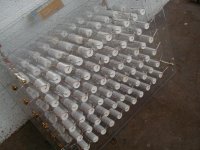
The 15kVAC MMC array - it is arrays of caps 15.000VAC
Geek Group MMC project
Here is a picture of one such Array 15kVAC:
I chacked in the homepage of one member
mbroker
http://www.diyaudio.com/forums/member.php?s=&action=getinfo&userid=1777
It is The Geek Group
http://www.thegeekgroup.org/
Check in The Projects, of this group.
They are into Tesla Experiments.
http://www.thegeekgroup.org/projects/index.html
THey have two projects with Making "DIY capacitors"
THese are used for storing the Energy
used in Tesla Explosions.
---------
Geek Bucket Cap
A Tesla coil capacitor for the budget coiler, the Bucket Cap is as simple and inexpensive as it gets. All you need is a 5 gallon bucket with tight-fitting lid, 12 empty longneck bottles, some wire, a little motor oil, and a whole lot of salt water. The Bucket Cap was The Geek Group's first Tesla Coil capacitor, and had been used for more than a year until the Geek MMC project made it obsolete.
Geek Bucket Cap
---------------
Geek Group MMC
This is the project that began the Geek MMC movement. With performance rivaling that of the big pulse caps, the Geek MMC is smaller, lighter, and much less expensive.
The 15kVAC MMC array - it is arrays of caps 15.000VAC
Geek Group MMC project
Here is a picture of one such Array 15kVAC:
Attachments
This would be easier with pictures, but let me see what I can do with words. It may come out sounding backwards.
Think of those plots you've seen of an incompletely filtered DC rail. You've got the average DC level...and superimposed on it there are sort of triangular AC bumps (120Hz assuming full wave rectification and 60Hz power) when the current hits coming in from the rectifier. The cap gets charged by the pulse of incoming juice from the rectifier, then it discharges into the load while waiting for the next pulse from the rectifier. Note that the voltage leaving the rectifier has to be higher than the voltage on the cap before current can begin to flow into the cap. (Kinda like trying to charge an already charged car battery with a 5V charger...won't work.)
When you've got a smaller cap, those pulses last for a finite period of time. The period of time will depend on the current draw from the circuit, the available current coming from the tranformer, and the storage capability of the cap.
With a larger cap, the average DC level remains higher, so the voltage coming from the rectifier has to reach a higher potential before it can begin to charge the cap. It will also drop below that average level sooner.
Now, here's the kicker.
<i>All</i> of the charging takes place during that little bump. Got to. Because no current can flow until the voltage exceeds what's on the cap.
Little cap=long time to charge (comparatively)
Big cap=short time to charge
Since the same amount of charging has to occur in either case, it's better to have a longer period of time to do it in.
Okay, on to the single cap bank vs. Pi or L or whatever. Think in terms of a speaker and this will be easier.
You've got a woofer and you want, say, a 100Hz rolloff, so you put on a cap in parallel (now you've got a 6 dB/oct slope). Works great. Except you're still hearing more midrange than you want. So you put on more capacitance. The result isn't quite what you'd hoped for. You've lowered the rolloff point (let's say to 75Hz) so the midrange hits a little bit different part of the slope...but it's still just a 6 dB/oct slope.
What you really want is to go back to 100Hz and use a sharper, higher order slope, like a 12 dB/oct or maybe even 18. So you stick in an inductor in series and another cap (adjusting values to keep it at 100Hz) and presto, you're getting better attenuation in the midrange.
Exactly the same for a power supply. You know what you want to filter--120Hz...actually anything above 0Hz, but really the first and worst harmonic is at 120Hz. So you try to get a "crossover" going that has a lot of attenuation before you get to 120Hz. More capacitance will move the "crossover point" down, but it's still just a 6 dB/oct slope. It's more efficient to put an inductor or resistor between two caps and make an 18 dB/oct slope out of it.
Yes, you can keep chaining these things out as far as you want. Real example: Sunfire tube preamp phono stage. There are six or eight stages in the power supply for the phono stage, all C-R-C-R-C...
Quiet as one could ask for.
That's not to say that big banks of caps aren't useful for raw Joules of storage, but that's another story.
Grey
Kilowatt for kWatts
Kilowatt - and he is not kidding ....
/halojoy - more like a milliWatt-amplifier man
Now I completely understand your User-name hereKilowatt said:Yes, I too am a member of the GeekGroup.
Kilowatt - and he is not kidding ....
/halojoy - more like a milliWatt-amplifier man
Hi Grey! Long time, no see!
The whole capacitor charge/discharge time can be looked at as a function of the resonant frequency of the capacitor's capacitance and the transformer's inductance. f=1/(2pi(sqrtLC)) where f is the resonant frequency in Hz, L is in H and C is in F. The charge time will be of this frequency, so the lower this frequency, the longer it takes to charge.
But it can also be looked at as a battery, or a HP filter, just like Grey stated, neither way lies.
Energy (in J)= 0.5CV^2 remember C is in Farads. This can also be used to find charge/discharge time.
I hope that's a typo, because it's absolutely not true. A big cap takes longer to charge. Try it sometime.Little cap=long time to charge (comparatively)
Big cap=short time to charge
The whole capacitor charge/discharge time can be looked at as a function of the resonant frequency of the capacitor's capacitance and the transformer's inductance. f=1/(2pi(sqrtLC)) where f is the resonant frequency in Hz, L is in H and C is in F. The charge time will be of this frequency, so the lower this frequency, the longer it takes to charge.
But it can also be looked at as a battery, or a HP filter, just like Grey stated, neither way lies.
Energy (in J)= 0.5CV^2 remember C is in Farads. This can also be used to find charge/discharge time.
Actually, I've been here for years (just haven't had too much audio projects going lately), much longer than I've been on the GeekGroup, but yes, I do love raw electric power, and have done cool stuf with it!Now I completely understand your User-name here
Reread what I wrote above.
We're talking the relative duration of the 'humps' above the average DC voltage present on the caps. There are diagrams about this in some, but not all, of the textbooks. A smaller cap bank will discharge more quickly, thus giving a slightly lower average DC value. Slight? Who cares? The rectifier cares. If you can double the time the rectifier has to pump charge into a cap, it'll run cooler. Now, granted, we're talking small fractions of a second here, but it makes a big difference.
I'll try to remember to take a look at Horowitz & Hill tonight when I get home and see if they've got the pictures I want. Have you got that book?
Grey
- Status
- This old topic is closed. If you want to reopen this topic, contact a moderator using the "Report Post" button.
- Home
- Amplifiers
- Solid State
- Capacitance Limit?