I have been playing around with various compensation, feedback techniques amongst the VAS stage and in a three stage design cannot figure out why more amplifiers dont use any compensation beyone a 100pf cap to tie the vas in heavy local feedback to stabilize.. To open this, ill state that the transistors i use in the differential are 2sc2705-y 200mhz devices with an average y beta gain of about 200. My Vas stage is a beta enhance emitter follower, the first bjt being 2sa1145, and second 2sa1360. This project has gone through many changes on punchboard prior to recenctly hand drawing out the PCB,s (talk about something that can make you tear your hair out)..I had previously been using a 47pf SM cap for local feedback and recently changed this down to a 10pf. I tied a 33pf SM from vas collector to the inverting input differential and WOW!, no longer did i have typical solid state somwhat etched treble, everything opened up and became an absolute joy to listen to, it was as if i had become surrounded by abolutely glorious music and textures that were hiding previously ,running circles around the second stage .. This fun lasted until I tightened the VBE multiplier to the heatsink and didnt notice a small burr from drilling the aluminum which punchered through the mica insulator. So after powering up and having the vas collector attached to a low impedence ground through the collector of the multiplier this power on took out the VAS transistor and let some smoke out of a 10 ohm rail resistor. But all is back in good health and sounds like music..
Colin
Colin
vynuhl.addict said:I have been playing around with various compensation, feedback techniques amongst the VAS stage and in a three stage design cannot figure out why more amplifiers dont use any compensation beyone a 100pf cap to tie the vas in heavy local feedback to stabilize..
Colin
Is a do ut des. With heavy local feedback, overall open loop gain decrease and left less room for compensating non linearities of the remaining amplifiers.
Because is not recommendable increasing open loop gain (that in turn increase side by side overall stability issues) increasing the number of amplifying stage, VAS stage is left relatively free of feedback, even taking in account that is not a major contributor in the overall distortion of the circuit.
Usually a three stage amplifier ("Self's fashon" if I can tell so) is arranged with the goal of reserving near the totality of open loop gain for improving PSRR and linearize output stage, the most "primitive" and "incorrectable" of the stages present in circuit. Input stage (usually differential) and VAS stage are linearized by design and, if proper care is paid, contribute very little to the total non-linearity of the amplifier.
Hi
Piercarlo
" I tied a 33pf SM from vas collector to the inverting input differential "
A bit like the Pass A-40?
http://www.passdiy.com/pdf/a40.pdf
And the earlier "Construct a Class-A Amplifier"?
http://www.passdiy.com/pdf/classa_amp.pdf
A bit like the Pass A-40?
http://www.passdiy.com/pdf/a40.pdf
And the earlier "Construct a Class-A Amplifier"?
http://www.passdiy.com/pdf/classa_amp.pdf
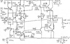
Yes, The pass a40 started my curiosity and the Rotel RB-03 also uses this concept, along with the leach although in a different way from the first driver emitter rather than the vas stage. It was sparked out of curiosity and to my ears unless someone can prove this cant possibly work it is staying says my ears. When I am not working, attending to my son or practicing with my 2 bands I spend my time studying schematics online and what I can get my hands on here and experimenting with some logical (wont burn the house down) ideas. I just was wondering why I see this concept used so sparsely in designs, aka next to none that i have found. I Have never heard the pass a40 but it must sound good..As far as a schematic goes im working on putting one together. My design was borrowed from doug selfs blameless, the same schematic that is on his site just reverse the whole front end up to the drivers and npns where pnp are used and likewise , i have separated the vas and differential current sources and have used an led based current source for the differentil at 4.5ma, and a two transistor current source for the VAS with a 68ohm resistor for approx 9.5ma.. I have paralelled two mjl3281/mjl1302 with 10ohm base resistors. the drivers are mjl15032/15033 which have 100ohm base resistors. feedback resistors are 22k1 instead of 10k and 1k instead on 500ohms. Feedback capacitor is a 1500uf 6v3 panasonic FC, without the protection diode. Input impedence is 22k1, paralelled with a 220pf polystyrene. I will work on putting a schematic up, even if it means drawing one up by hand and scanning it.. )
)
Colin
Colin
)Colin
Colin
Hi,
three British manufacturers/designers that I know about do it this way, Sugden, Crimson, JLH. The Sugden and JLH schematics are on the Forum.
Cordell has written about it.
Many use the two stage feedback but it takes more skill and usually more components and is less tolerant of production spreads.
The reason most go Miller comp cap is that it is easy and particularly suited to production line tolerances and here in the Forum because it's foolproof and does not need stability to be checked with a scope and some skill.
That capacitor in the feedback transistor is interesting...already used by Graham.
Another interesting use is to install an RF variable capacitor...from 10 to 100 picofarads into the feedback line..in parallel with the feedback resistor.
Now insert FM inter station hiss and turn the potenciometer to peak the max possible hiss level and/or quality.
Remove the variable capacitor and measure....now substitute it by a fixed silver mica resistor...ready...a tuned amplifier to its maximum capacities.
Suggestion came from Graham Maynard, i made it in the practical world...over a circuit...it was tuned and sounding great...value was 15 picofarads..very hard to adjust with a 10 to 100 picofarads variable capacitor....This is BRA...created by Brain...tested Real world and evaluated by Audition
Graham knowledge is for free..here is a link of his amplifiers:
http://www.gmweb2.net./
regards,
Carlos
Attachments

vynuhl.addict said:I tied a 33pf SM from vas collector to the inverting input differential
and WOW!, no longer did i have typical solid state somewhat etched treble ...
Colin
QSerraTico_Tico[/i] [B]Can you post schematic Colin? Talks a little easier. [/B][/QUOTE][QUOTE][i]Originally posted by djk said:" I tied a 33pf SM from vas collector to the inverting input differential "
A bit like the Pass A-40?
Here is the schematic for QSerraTico_Tico
which shows what vynuhl.addict is doing.
As djk tells, this was used is Nelson Pass A40 amplifier.
Nelson mentions a value of ~40pF for this cap C4.
An externally hosted image should be here but it was not working when we last tested it.
regards, lineup
Thanks for the post of the a40 Lineup. Carlos, this cap your are talking about is similar to what is used across the symasym 22k feedback resistor with an original value of 22pf changed to 10pf if i am correct?. I have noticed that the pre 1983 krell ksa-50 uses a 20pf to base, and the ksa100 uses a 10pf to base with 39pf lag compensation. I really wish I had access to measuring equipment to get greater insight beyone my subjective ear measurements. But things seem to be running smoothly, and all test points measure like they should for current drawn by each stage 138mv across the 10ohm rail resistor 13.8-14ma drawn by the first two stages, so nothing wild happening. I still have the vas wrapped in miller compensation except a very low 10pf value with the 33pf acting as a high frequency feedforward bypassing completely the "slow" output stage.
I just tried this on my Gilmore Dynahi amp, from the cathode of the second stage off the positive rail, to the inverting input, using just 10pF. Not shown in the attachment is my feedback network of output/1.21k bypassed with 47pF/inverting input/100R to ground. Very noticable and enjoyable. I'll try some other values as I'm able to find them in the mess I call a work bench.
I drink a toast to Nelson Pass.
I drink a toast to Nelson Pass.
Attachments
Earlier examples of that cap
The revised version (by Dynaco) of the Stereo 120 Power Amplifier had that cap. It's C15 in the schematic pointed to by the following link...
http://www.updatemydynaco.com/pictures/stereo_120_later_schematic.png
The revised version (by Dynaco) of the Stereo 120 Power Amplifier had that cap. It's C15 in the schematic pointed to by the following link...
http://www.updatemydynaco.com/pictures/stereo_120_later_schematic.png
vynhul.addict, the 33pf cap you have added is Miller Inclusive Compensation (MIC). It is possible to remove the miller cap completely using MIC (that's your 10pf cap above) but you may then need to provide some additional compensation to keep the front end stable. Bob Cordell discusses this technique in quite some depth in his book.
What you have done with your amp is reduced the overall loop gain, and probably made your amplifer more stable and provided greater phase margin. This may well be why (but I am only surmising here) why it sounds better. Overall distortion is probably a bit higher (because there is less feedback around the output stage), but your amp better behaved. There are some more advanced compensation techniques like TMC that can overcome this as well, but MIC is a good start and much better than simply loading the VAS which was the old style way of solving the problem.
Re the cap in parallel with the feedback resistor, if you select the value correctly (and that means the R/C combo frequency will probably need to be set at about 5-6MHz), you can gain yourself another 10-15 degrees of phase margin (3-6dB gain margin). Typical values are in the low single digit pF's for feedback resistor values of c 5K Ohms. If you make the value too high, you end up causing overshoot and actually can cause the amp t break into oscillation. A potential issue with this approach is the possibility of introducing RF picked up from your speaker cables directly into the base of the front end diff amp - so be careful.
BTW, I think you amp would benefit from a small output inductor of around 1uH located directly after the Zobel - this would provide you with additional stability margin by isolating your cable and speaker capacitve load at HF.
- Status
- This old topic is closed. If you want to reopen this topic, contact a moderator using the "Report Post" button.
- Home
- Amplifiers
- Solid State
- VAS, the stage that makes or breaks audio nirvana??