I am thinking to call it Dx Boom
Because this is what it gonna make...a big boom in our home.
Not decided yet.... i do think Destrodom is nice... Destrodoom...but too much long...better to be something that connects to Dx to make a good sound.... try to pronunciate Dx XS..... this is a good idea.... also Dx Doom sounds nice.
The undestructable Dx unit had lack of interest, i have published and nobody made comments...so.... was not a good idea...... as good idea are the ones people comes to enjoy/help/criticise or bomb...... say, reactions must exist...positive or negative.... XS continue to be a great name but the amplifier design was abandoned.
I am already designing...now trying different options to the thermal control...power will be higher than 1.350 Kilowatt.... 24 output pairs.
Heheheheheh.... of course people can reduce matching to the available transformer power they may have/buy/borrow/make or order...so.... to less power people can use 10 pairs.... and even less, depending their supply voltage, heatsink size, rectifiers power, electrolitic condensers available, enclosure size and other details.
regards,
Carlos
Mr. Carlos Sir,,I,m glad to hear your getting back into the MOOD again, I,m looking forward to hearing what you can produce with such a large power amp. Just a suggestion make it a 5 pcb design this way you,ll turn off the copy thieves, EX:1 pcb for input+driver 1 pcb for front end power supply 1 pcb for bias control 1 pcb for protection output 1 pcb for output supply. Make it as diffuct as possible to copy it For Them. Just my $.02. Regards Evette
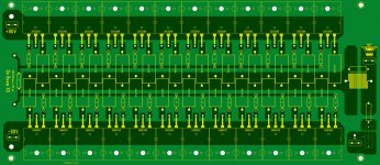
Hi Carlos what you think about this layout is a eraser for ideas not need to be the final product just a mud sculpture to more ideas and tweaks I mean illustrations I hope Herman can see it too.
Regards
vargasmongo3435
Regards
vargasmongo3435
Attachments
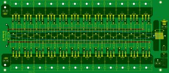
Ok here is my last concept ideas of today my brain is toasted lol I just got from mail the aluminum heat sink I need it to completed my Dx Blame MKII Supercharged hell yeah! see ya later guys! weeeeeeeeeeeeeeeeeeeeeeeeeeeeeeeeeeeeeuuuuuu! 
Regards
vargasmongo3435
I just got from mail the aluminum heat sink I need it to completed my Dx Blame MKII Supercharged hell yeah! see ya later guys! weeeeeeeeeeeeeeeeeeeeeeeeeeeeeeeeeeeeeuuuuuu! Regards
vargasmongo3435
Attachments
Ok here is my last concept ideas of today my brain is toasted lol
Regards
vargasmongo3435
What program did you use to draw this with?

What is going on about the Dx amplifier for Bass - 90V supplies
and passive input filter...... now i gonna inform you what is going on:
The decision about this amplifier, when we have more modern circuits, is because the special kind of bass it reproduces...longer and deeper than the real world source bass....to the ones appreciates nice sonics more than nice numbers.
Two guys are working to produce the layout, one is Juan Vargas from Puerto Rico and another is Renato Comerlatte from São Paulo - Brasil...both are working independently but i am tracking their work and giving them some uncle charlie inputs...one wants electrolitic condensers in the output board..other do not want...so..we gonna have both options.
Here a text about what is going on, an image will be posted for you to see the circuit (without part values for a while).... and i will post, this time, firstly in English and then in Portuguese:
Was my mistake the quantity of output transistors boys... you should prepare output pcboards to use 10 pairs or 20 transistors as the maximum quantity really needed to use together a 2 ohms impedance speakers at maximum power... to use 4 ohms loads, we may use 6 pairs (who knows..i have to check in the simulator)..... to 8 ohms loads maybe 4 pairs will be good.... the real output power (depends on transformer power) will be 400, 800 and 1.3 Kilowatts aproximatelly to 8,4 and 2 ohms loads.
I will check this with the at clipping to see the current needed, less than 1 A to each power transistor as passing through current (because some transistors are not that strong ..example is 2SC5200 that cannot face more than 1 Ampere (SOA) at 90 volts...and then i will inform...for a while i am creating the amplifier, and trying to reduce the harmonic distortion to 35 hertz.
Input filter is passive...and it has losses in level that may be almost 3db at 40 hertz, 8 db at 250 hertz, 14 db at 500 hertz and more than 20 db at 1 kilohertz..so...it works...but introduces reduction of level in input asking for the amplifier more gain and more sensitivity..also i will be forced to insulate it from the audio source in order not to filter the audio source high frequencies tones...maybe this force me to change my mind to make active circuit to be used in in the input.
Distortion to 35 hertz and 53 volts AC RMS of output voltage is around 0.6 percent into 4 ohms loads and 700 watts RMS of output power...too high..i am trying to reduce it despite the Dx amplifier usually is 0.03% of total harmonic distortion to 8 ohms and 50 watts rms ..... and these numbers increases a lot when you increase supply voltage and reduce the output impedance.
For a while, calculator machine and simulator is being use...soon i will assemble the prototype to listen
Now in portuguese... aprox. the same text in portuguese... same meaning, same informs, same central idea:
Foi engano meu... 10 pares ou 20 transistores é o máximo necessário para usar 2 ohms.... para 4 ohms talvez possamos usar 6 pares (quem sabe..tenho que verificar) e para 8 ohms poderemos usar uns 4 pares (quem sabe?... tenho que simular).... a potencia é de uns 400 para 8 ohms...uns 800 para 4 ohms e 1.3 Kilo watts para 2 ohms...então a turma pode serrar a placa...faz para 10 pares de forma que possam serrar (cortar) a placa.
Eu vou verificar essa situação verificando a corrente circulante, por cada transistor no ceifamento (clipping)... você deve preparar placas para usar 10 pares ou 20 transistores (vocês; Juan Vargas e Renato Comerlatte).... e essa deve ser a maior quantidade para enfrentar a maxima potência quando tivermos 2 ohms ligados na saída do amplificador.... para usar a unidade com alto falantes de 4 ohms, nós talvez venhamos a usar uns 6 pares aproximadamente (não sei ainda..vou verificar).... e para 8 ohms talvez possamos usar 4 pares apenas.... a potencia real, aproximada (depende da potencia do transformador) será aproximadamente 400,800 e 1.3 kilo watts correspondentemente a 8,4 e 2 ohms.
O filtro de entrada é passivo...e as perdas são de 3db em 40 ciclos, 8db em 250 ciclos e 14db em 500 hertz.....havendo mais de 20 decibéis perto de 1 Kilo ciclo (aproximadamente..nada preciso..só pra te dar uma idéia da coisa)... o uso de passivos reduz o nível de sinal e obriga que aumentemos a sensibilidade (o ganho) do amplificador para compensar....e isso costuma gerar instabilidades...por isso talvez eu repense esse circuito passivo na entrada êda fonte de sinal para o terra.
Por enquanto, a distorção para a frequência de 35 ciclos e 53 volts AC RMS de saída, está próxima a 0.6% em 4 ohms quando o amplificador produz 700 watts RMS...muito alto isso... vou tentar reduzir, apesar do Dx amplifier usualmente exibir distorção de 0.03% quando alimentado com apenas 35 volts, na impedância de 8 ohms e com potencia de saída de 50 watts RMS..quando aumentamos a tensão no Dx amplifier, e quando aumentamos a corrente e a potência, reduzindo a impedância dos falantes, então temos um incremento violento na distorção harmônica...coisa que eu pretendo reduzir um pouco.
Por enquanto eu estou usando maquina de calcular e simulator....mas dentro em breve (neste fim de semana)...vou montar protótipo e testar a sonoridade
Regards,
Carlos
Attachments
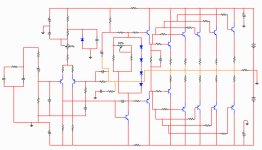
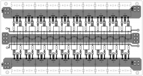
I have cleaned the schematic a little bit
It almost ready to 4 ohms loads...more than 700 watts RMS at 35 hertz with less than 0.6% distortion.
To the ones are preparing pcboard:
Supply rail condensers are huge...left side (input side) is 1000uf/100V and to the right side we have 2200uf/100V...they are big in size...and soon they gonna have small capacitor in parallel...circuit is not ready.
The heat sensor diodes are high speed TO220 devices, made of plastic (have plasticity, you can make shape with that material) and the internal junction is electrically insulated from the heatsink.
I will try big transistors (output units) as drivers and maybe as VAS...so...it is not a good idea to prepare pcboard for a while.
regards,
Carlos
Attachments

Last edited:
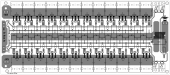
Ok for now no board till you got all figure out is cool I was checking about the 10 top and 10 bottom I just got a concept art is just a draft.... to see how it looks only...
ok Carlos I'm not going to place drawings until you get all figure out I don't want the forum to get confuse from so many images, and "ideas drawings" it has to be solid concept from you and then it can be sculpture with the help of Renato and me till then is on the chalk board. "did I said that correctly"?
Regards
vargasmongo3435
to see how it looks only...ok Carlos I'm not going to place drawings until you get all figure out I don't want the forum to get confuse from so many images, and "ideas drawings" it has to be solid concept from you and then it can be sculpture with the help of Renato and me till then is on the chalk board. "did I said that correctly"?
Regards
vargasmongo3435
Attachments
Last edited:
I do like it dear Juan.
It is time to people to present ideas.....this is the moment and i have to thank you and also Renato because both of you are cooperating.
If you read the past, you gonna see that i dislike to make layout, and always people made them for us.... and i love that...and i hate to make layout....so...you are making a big favor to me and to all of us DIY builders.
regards,
Carlos
20 output transistors per channel? That is going to be a monster! Do you really need that much power? My diy amp is around 70 watts RMS per channel and I do not see the need for more power than that, beside my speakers are 90db spl so they get really loud. Can you post your Destroyer amp that you finished, I never saw it in the solid stated pictures
20 output transistors per channel? That is going to be a monster! Do you really need that much power? My diy amp is around 70 watts RMS per channel and I do not see the need for more power than that, beside my speakers are 90db spl so they get really loud. Can you post your Destroyer amp that you finished, I never saw it in the solid stated pictures
This way you've a lot of headroom
It will not be really a 20 output transistors..this is to the worst case scenario
This gonna be needed if you manage to find/buy or build a real 2.5 kilowatts power supply to each channel...but it is hard to do that.
Also when draining energy from power supplies, the voltage drop down.... and this reduces the need of so many transistors... power is voltage multiplied by current.... when voltage drops, the result of the multiplication also reduces...the power reduces..... with reduce power you can reduce transistor quantity.... each case will be examined with a lot of care in the future, because people will not use 90V and will also find different values of VA rating to power transformers too.
This gonna be needed (all twenty transistors) if you decide to use a very complicated 2 ohms speaker, these ones have internal crossovers and valleys of impedance in some frequency.... i do not think people will do that because no one is stupid.
So, depending your transformer power, depending your heatsink size...depending your electrolitic condensers capacity...then you will manage how to reduce that.
I will inform latter, because the amplifier is in the early prototype moment, how many transistor may be needed to 8 ohms and to 4 ohms...maybe much less than that gonna be needed.... please, read the text published because it explains that in two languages.
It is a very good idea to read the thread in advance to post comments.... your message, dear friend Lanchile, proves that you have not readed post 7092... go there and take a look.
I have instructed layout designers (by email) to make the pcboard in such way builders will be able to use a hacksaw to cut it, so, they gonna be able (builders) to decide the quantity of output transistors they gonna need in accordance to their power transformer VA rating, heatsink size, electrolic condensers available, size of his enclosure, number of channels inside the enclosure and details like that.
regards,
Carlos
Last edited:
- Status
- Not open for further replies.
- Home
- Amplifiers
- Solid State
- Destroyer x Amplifier...Dx amp...my amplifier