Initial power-on
Hi,
Tonight I made the initial power-on of my amp, things seems positive in a general sense (no smoke...). I'm able to adjust the bias level to about 100mA using 10ohm sense resistors instead of the fuses, but there seems to be some oscillations related to the bias level.
If I put a scope on the speker output there is a sinewave (with the input shorted) at around 16MHz, the amplitude varies with the bias level but is around 50mV with a bias level of 100mA. If I increase the bias level to around 120mA the output amplitude goes up a lot and the current across the 10ohm sense resistors goes up to around 700mA and stays there until a turn off the power.
Touching the trimpot on the bias "board" with a finger makes the output amplitude drop, so I suspect that this arrangement is not completely stable. I assume this behaviour is not normal, is it? Should I adjust some component values?
Thanks
Daniel
From London to Brasil...
...I'm sure he'll be looking forward to it! We've had such a poor summer I bet he'd much rather be there than here.
Although I was in Kefalonia, Greece, last year when it got up to 43-44 deg C some days. I'd never felt heat like that before. They had huge problems with bush fires - we watched the fire planes picking up sea water to put them out (fun to watch, but a bit unnerving to see fire and smoke on the hills).
Back to the DX - a quick question about volume control - just a potentiometer in series to the signal input?
Thanks,
Darren
Yes Forever...put a potentiometer and be happy
Dnilsson..... 50 milivolts is a very small signal... seems you are picking some nearby oscilator.... 300 microwatts of power into 16 Megahertz i think will not bother your ears or speaker, or circuits.
Check your input condenser, your feedback condenser and the miller condenser.... increase the miller condenser you have into the VAS.... observe if you have connected the zobel to ground..this is made with an external wire.
Check your scope with your amplifier out from the scope probe points and switch the power amplifier supply off.... pick a good piece of wire and connect to your scope to observe if your signal remains.
Really.... this is the first time i listen that kind of problem....well... if you understand as problem..because 300 microwatts is not a big problem inside my mind...maybe you feel unsafe with this signal you found.
This frequency can come from everywere... a lot of appliances have oscilators transmiting clock signals around you... even some instruments produces some spurious signals.
If was amplifier oscilation you would have 50 volts peak to peak into this frequency... not 50 milivolts
regards,
Carlos
Just to remember you Forever.... there are two most common uses to
Install potentiometers.
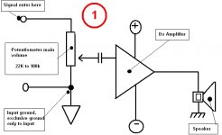
The first one is more often used... it "loads" the power amplifier input as the power amplifier "will see" a variable resistance to ground (if amplifiers have eyes to see... means feel).
The power amplifier has an input condenser...so...this will not bother the input circuit biasing... base will remain with the needed voltage there.... electrolitic condenser into the input will have the negative pointed to the ground...so....no problems to "put the power input to ground.... means.... AC to ground"
This sketch (scratch) signed "A" will present a stable resistance to the audio source... as the audio source will "see...or feel" a stable resistance to ground.... and high resistance to ground...so...even if you have no output coupling condenser (blocking DC) into your CD DAC output, you will not face problems.
See the first sketch... the number 1
...numberone.... this sounds good...excelent name for my next amplifier....numberone!
Dx Amplifier does not bother using this connection... the unit is stable and this does not represent any problem to the amplifier input circuitry.
regards,
Carlos
Install potentiometers.
The first one is more often used... it "loads" the power amplifier input as the power amplifier "will see" a variable resistance to ground (if amplifiers have eyes to see... means feel).
The power amplifier has an input condenser...so...this will not bother the input circuit biasing... base will remain with the needed voltage there.... electrolitic condenser into the input will have the negative pointed to the ground...so....no problems to "put the power input to ground.... means.... AC to ground"
This sketch (scratch) signed "A" will present a stable resistance to the audio source... as the audio source will "see...or feel" a stable resistance to ground.... and high resistance to ground...so...even if you have no output coupling condenser (blocking DC) into your CD DAC output, you will not face problems.
See the first sketch... the number 1
...numberone.... this sounds good...excelent name for my next amplifier....numberone!
Dx Amplifier does not bother using this connection... the unit is stable and this does not represent any problem to the amplifier input circuitry.
regards,
Carlos
Attachments
This other way.... of course there are other ways...
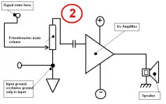
But those are the most often used..... this other way is good to the power amplifier... some of them can operate without input condenser... the trimpot will be the base resistance to ground... a fixed resistance.....BUT...... the source equipment will face something that can be a problem.... the lowest volume put the output "live" wire connected to ground as a short...this sometimes is a problem when source equipment does not have output condenser..
Also the source will "see and feel" a variable resistance to its output stage... this may be bad sometimes... when you adjust the resistance will change from the "live" wire to ground.
Of course you can use another condenser into the input....but those folks...potentiomenter input condenser and the power amplifier input condenser will be in series one respect to the other... this will need you to increase both not to have losses into the low end.
Well... this is very basic things...do not be offended with big old fat uncle Charlie..... i am just trying to help... i have no "cristal ball" or "sonar"....no "radar" to discover how much you know... you can be better than me about those things and i am writting foolishes to you....but.... for sure there are young beginners that will appreciate those informs.
See sketch number 2
regards,
Carlos
Attachments
I am a complete beginner...
When it comes to amplifiers, dealing with mains power, etc, I know next to nothing - I've read most of this huge thread and picked up a little knowledge here and there, but in all honesty I'm simply building the circuits out of a passion for hi-fi ... which will often mean that I'll go without understanding them!
So a big thank you, uncle Charlie, for the diagrams above - I wouldn't have known to set up the volume in this way. I know my questions will be rudimentary to many on this forum, however I hope you don't mind me asking them.
All the best,
Darren
Carlos,
" A bull ship---- a big boat filled with cows"
Be kind to cows, you never know when you might want to eat one.
http://images.google.co.uk/imgres?i...bnw=123&prev=/images?q=Funny+cows&gbv=2&hl=en
" A bull ship---- a big boat filled with cows"
Be kind to cows, you never know when you might want to eat one.
http://images.google.co.uk/imgres?i...bnw=123&prev=/images?q=Funny+cows&gbv=2&hl=en
Oscillations...
Hi Carlos,
I made some more measurements, first of all I'm not at all worried that the 300uW of power at 16MHz would harm anything so I don't consider that a problem. What worries me though is that the amplitude of the oscillation depends on the bias level. At 0mA bias, there is 0mV of oscillation amplitude at the amplifier output. At 100mA bias there is about 50mV (peak) of oscillation amplitude. This might be fine, but the bias level seems very hard to adjust and it depends on the temperature. In fact, the bias current increases constantly as the amplifier warms up. Once the bias current goes above 110mA (either by adjustment or by warming up) the bias current suddenly jumps to about 700mA and can't be adjusted back down. I have to turn off the amp and turn it back on for the bias current to be adjustable again. Maybe this is not related to the oscillation seen at the output, I just though it might be...
Anyway, with the amplifier off there is no noise picked up by the scope. The frequency of the oscillation also varies with the bias current level so I'm pretty sure it is not coming from a nearby clock source. Touching any of the pins of the BD139 transistor mounted on the bias servo with a screwdriver also makes the oscillation go away.
I started wondering why the bias level is not drifting and remembered something... I bought the component kits from Nordic but my kit was lacking one pair of BD139 transistors. I bought another pair and mounted in position Q8 (one transistor for each channel). So Q8 is a different brand compared to Q6, Q7, Q9, Q10 and Q13. Maybe this was not a good choice? Looking at the circuit a little closer I suspect there are some assumption maybe regarding the gain of Q8 compared to the drivers and Q13?
I checked the input capacitor again, it is 2.2uF. Which one if the feedback and which one is the miller capacitor?
Trying to attach a picture of the current state as well...
Thanks
Daniel
Attachments
Oops...
Hi Carlos,
I checked Q8 once more, it turns out that I got a high-gain version of BD139 from fairchild by mistake which is now mounted in position Q8. HFE classification 16 which means HFE of 100-250. See:
http://www.fairchildsemi.com/ds/BD/BD139.pdf
I assume this is not good, I will attempt to find a normal BD139 and replace Q8 if you think this seems like a potential source of my bias "runaway" tendencies...
Thanks
Daniel
So the bias is getting mad..... and the RF changes with bias
You really have something strange there.
Man.... i have made modifications into this amplifier... and i have two board running stable here... i have to find time and patience (as something already done, almost finished and back once again to live) to check all parts values into my boards to inform you.
For a while...hopping you are still listening and enjoying the amplifier, as even with bias jumping wrongly it may produce nice sonics (if not oscilating.... the one triggered with signal).... for a while send me your mail adress.... them i will send you high resolution (4 Megapixels) picture from the board..with the resistances i am using and working great.
Remember those heaters.... the class A amplifiers works with 2 or more amperes into stand by mode.. dissipating more than 60 watts each channel...so...your 700 miliamperes may be easy for your system to hold for a while.
I am using BC556 and BC546 ... also BD139 and BD140... even to VAS...into the output 2SC5200 and 2SA1943 and 36 volts plus and minus into the supply.
Mine has no problem.. i am not using any condenser into the thermal sensor transistor...the one assembled outside the main board... and my on board condensers are all 220uf.
My supply is 12.000uf each rail.... the supply is mine one..with snubbers and coils.... the one folks believe as done into an overkill way.
write to big Charlie.... and i will send you the picture...the board operating..no strange things happening, no thermal drift, no misterious thing and i have not the scope to bother myself with this 16 Megahertz you have found...if it exists into my board have never worried me.
Now a days, as you told me... everything happened in my home.... the refrigerator damaged...the amplifier noisy... the shoe producing pains into my toes, the hot iron to pants... the micro wave, television and plumbing problems .... well... they will drive me worried... because now i know!...maybe the 16 megahertz you have told me.
Into those moments i feel an advantage not to have scopes here...the simulator has show me nothing.... nice simulator.
panzertoo@yahoo.com
Have you something alike a "knee"... some point where bias jumps higher... when you go adjusting them it jumps fast to a very high value?
regards,
Carlos
Measure your output VBEs and inform Dnilsson
Also the drivers VBE..... and inform the resistance value you are using into the drivers emitters...this is a hell important.
Not only inform but also take your multimeter and measure this resistance... the floating one..... used normally there goes from 100 to 220 ohms.
The drivers must measure higher VBE than the output ones...but if output ones are near 500 milivolts..then you have the "knee".... that crazy point when you bias jumps to 700 miliamps.
regards,
Carlos
Well... pictures ready... waiting your E mail adress
I am trying to remember..... i have made so many amplifiers after this one that i cannot remember details anymore.
Well...the big thread must have all informations.... also the one Nordic have openned as group buy.
In the reality...the amplifier is so old now a days... as i have made so long time ago.... around a year or more ago.... i cannot remember all details about.
Here is a sample about 2 pictures i have made.... they are not so big.... 2.5 Megapixels each one... then you will be able to watch to search for differences.
regards,
Carlos
Attachments
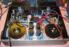
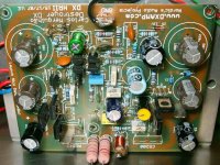
Here is a reduced image....maybe will be helpfull.
Power transistors are under the board as i had no room enougth to place them the way i like.
Also the bias control (fixed, pré adjusted with resistances) is under the board.
Sorry, board not cleaned.
regards,
Carlos
Power transistors are under the board as i had no room enougth to place them the way i like.
Also the bias control (fixed, pré adjusted with resistances) is under the board.
Sorry, board not cleaned.
regards,
Carlos
Attachments
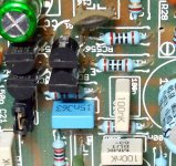
Dnilsson... the capacitor informations and others
C12 is the feedback one.... can be 10 pf or increased till 27 picofarads
C18 is the Miller one.... it is 47pf but you can increase it till 100pf to block oscilations (if needed)
C27 is the Zobel filter capacitor...under the board you must run a wire from this capacitor to the ground... general ground...NOT THE INPUT ONE!
C3 is the Radio Frequency input filter... band pass capacitor
IMPORTANT.... change R20 to 180 ohms...into the schematic it is 150 ohms.
Do not forget zobel wire... also output coil (not critical values there).... this coil is there only to remove a over shot into the signal into 10 kilohertz i think (if i can remember things from the last year.... i have made more than 40 amplifiers before).
schematic:
http://users.tpg.com.au/users/gerskine/dxamp/dx hrii amplifier green.pdf
regards,
Carlos
Attachments

I'm having a small break about build things.
I am a little bit tired of this long and insane search of perfection.
A friend, in Australia, seems have found the best amplifier.... he bougth and he is listening.... first evaluations were great...i am waiting his next feedback in a couple of days or weeks....them i
will know what he really have perceived.
Well...maybe he could find something i could not...i am waiting for him to inform me about.
I have a lot of good ones, some are excelent...others awsome...many brands and DIY circuits too ...but no one is perfect.
The guy is evaluating, has almost all DIY kits in his home...also he likes the same amplifiers i like...also he has a lot of commercial units and the ones he appreciate are the best ones..not only in my judgment but they are understood as better by many reviewers...so...if he really found the best.... small doubts will remain to test...probably will be really the best, and them the idea is to assemble, to listen and to buy the commercial unit too.
regards,
Carlos
Attachments
Amplifier measurements
Hi Carlos,
First of all, lets use reference designators from the schematics you are referring to:
http://users.tpg.com.au/users/gerskine/dxamp/dx hrii amplifier green.pdf
I replaced the BD139 transistor in location Q7 according to this schematics with a standard BD139 (not the high gain version that I had accidentally bought). That made the bias adjustment a little easier to perform, but there is still a jump around 110mA up to 700mA.
I've built my HR II according to:
https://www.dxamp.com/images/DxHRII_v.F_brd.pdf
So R20 is already 180 ohms. I've measured the resistance to 179.4 ohms in the actual circuit. The VBEs are measured like this:
Negative side: 578mV across 2SA1943 and 596mV across the driver.
Positive side: 588mV across 2SC5200 and 601mV across the driver.
My feedback cap is 10pF (MICA). The miller cap is 33pF (MICA). The zobel network is connected through a wire to the GND spade on the board.
What I noted though is the the capacitor C21 that is mounted across Q6 is missing on Nordics schematics that I've built according to. I tried adding this cap to my amp, but that made the bias level very difficult to adjust. I either had no bias or the 16MHz oscillation would start and the bias level jump to 700mA.
Are you not using a bias servo at all on your designs? The instability I'm observing around the 100mA bias level seems related to the 16MHz oscillation which in turn seems related to the circuit around Q6. Q6 in my case in mounted on a small board directly the heatsink.
I've also tried increasing C18 to 250pF but that didn't make a difference. Adjusting the bias level down to 50mA makes the oscillation go away though and it seems to result in an amp with a stable bias level even when the amp warms up (tried heating with a hair dryer...). Maybe that is the best option I have? Adding a small cap 220pF across CE on Q5 also makes the oscillation go away.
Thanks
Daniel
I hope it is sounding fine as it seems very strange
effects (or deffects) it is offering you.
I am sorry, but i do not know what is going on.... very strange things.
Enjoy the sonics, at least the unit may be sounding great.
VBEs seems good, also the stand by current.
regards,
Carlos
....................................................................................................
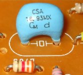
Sometimes we face strange signals, some spurious, some non filtered signals generated inside our own audio system...here you see the "clock" generator, an auxiliary oscilator used into old CD readers.... i think this is not your case....but happens sometimes with many folks.
I could see people "scratching their heads" with strange signals readed into the scope screen.... and once it was generated inside the scope.
effects (or deffects) it is offering you.
I am sorry, but i do not know what is going on.... very strange things.
Enjoy the sonics, at least the unit may be sounding great.
VBEs seems good, also the stand by current.
regards,
Carlos
....................................................................................................
Sometimes we face strange signals, some spurious, some non filtered signals generated inside our own audio system...here you see the "clock" generator, an auxiliary oscilator used into old CD readers.... i think this is not your case....but happens sometimes with many folks.
I could see people "scratching their heads" with strange signals readed into the scope screen.... and once it was generated inside the scope.
Attachments
- Status
- Not open for further replies.
- Home
- Amplifiers
- Solid State
- Destroyer x Amplifier...Dx amp...my amplifier