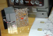
This one will cook your transistors.... even using one to each power transistor
Using blower and 8 ohms speaker....not enought.
If you sustain a tone..... some sustain instrument that produces continuous tone, and for long time, the heat will go above the limits.
regards,
Carlos
Using blower and 8 ohms speaker....not enought.
If you sustain a tone..... some sustain instrument that produces continuous tone, and for long time, the heat will go above the limits.
regards,
Carlos
Attachments

Re: I have some little...
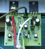
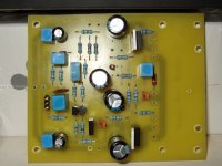
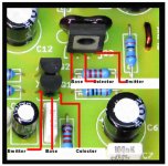
Just to be clear confirming ecat last point. The Vbe multiplier transistor Q8 has to be mounted on the same heatsink close to one of the output transistors. This transistor Q8 senses the temperature of the output transistors and reduces the bias when they heat up, thus preventing thermal runaway.
See in the picture, I attached mine right on top of Q6. This saves drilling an extra hole and reduces thermal lag. A trick I picked while building my AKSA.
regards
microp said:heatsink's from pc motherboards... I will attach them to transistors... I think it would be enough.
Just to be clear confirming ecat last point. The Vbe multiplier transistor Q8 has to be mounted on the same heatsink close to one of the output transistors. This transistor Q8 senses the temperature of the output transistors and reduces the bias when they heat up, thus preventing thermal runaway.
See in the picture, I attached mine right on top of Q6. This saves drilling an extra hole and reduces thermal lag. A trick I picked while building my AKSA.
regards
Attachments

Re: Re: I have some little...
Greg Erskine said:
This transistor Q8 senses the temperature of the output transistors and reduces the bias when they heat up, thus preventing thermal runaway.
Thanks!!! I didn't know it...
Re: Re: I have some little...
Or on top of <chuckle>. I was going to mount mine on the heatsink right in the middle of the op transistors, would this be a problem ?
Greg Erskine said:
... close to one of the output transistors.
regards
Or on top of <chuckle>. I was going to mount mine on the heatsink right in the middle of the op transistors, would this be a problem ?
hi ecat,
Probably not. There are plently of layouts like the one you suggest.
If you imagine the output transistor heating up, it takes time for the heat to reach the mid point between the two output transistors. This is the thermal lag I was talking about. It just means Q8 will be a little slower to compensate. So at a guess, I haven't done tests, the bias will vary over a greater range.
hi microp,
If you use a multi turn pot for Vbias (VR3), it will make setting the bias accurately easier. I see you're using one for VR1.
regards
Re: I felt a little bit more controled, the bass, reducing it since the input.
Hello
I remember Hugh Dean, in a 2004 Aksa thread, say that the 0.47 ohms emitter resistances was for the output to have more linearity.
What do you mean "producing nice figure at numbers" is it the soundstage ?
I do learn a lot in the Dx amp thread.
Gaetan
destroyer X said:
Try to install a 82N capacitor into the input.. substituting others that you have there... a single one to block subsonic and attenuate low end
Try to reduce R11 to 33K
Reduce C10 to 100uf
Install 0.47 ohms emitter resistances under the board.... this is the worst modifications i think, because turn the bass more controlable, less loosen but also much less punchy...the thunderstorm punch of the bass is lost in the name of superb fidelity, astonishing quality and impressive capacity to hold instruments producing nice figure at numbers......
...
regards,
Carlos
Hello
I remember Hugh Dean, in a 2004 Aksa thread, say that the 0.47 ohms emitter resistances was for the output to have more linearity.
What do you mean "producing nice figure at numbers" is it the soundstage ?
I do learn a lot in the Dx amp thread.
Gaetan
It is very impressive how fast you are Ecat..... also Microp is working fast too
I am happy to see you both moving.
Related emitter resistance...the standard Dx amplifier has not those resistances as you know.
About the sonic differences, give a try in your own unit...one channel with emitter resistance and the other using it...and compare.
I think the best way to conclude things is to listen.
regards,
Carlos
Hey Ali-X,
why don't you do us a favor, dress up as Eduardo and stroll into the Audiopax building to shop for a single-ended transistor amp some folks would like to peekaboo inside.
You've had a towel around your head, as long as you haul the merchandise you can wear a lady pantyhose for what i care.
(Rua Alvaro Alvim 31/1302, Rio de Janitor)
Naah Vermeullen
Naah!
I have born in Rio de Janeiro city..... Alvaro Alvim is there!...say...the street.
I am in Recife.... around 2 thousand miles into Northeast direction.... i do not feel we have Alvaro Alvim, Avenue or street, here.
Also i do not understand English very well...decode messages as i cannot read them coded...because poor English reading.
regards,
Carlos
Attachments


Re: Transistor position will depend of the unit selected
Indeed, it would by typical of me to forget. From now on I'll fit the jumpers at the start while fitting the resistors")
The other component that I would typically get wrong is C12 the 47uf 70v capacitor. I totally missed this when buying parts, luckily the local store had 5 100v parts and I found a 6th in an old TV
This is where the pictures of everyone's boards can become very confusing, I know I've had to check and double check and draw a picture and have a coffee and check again - lol, very confusing. For the record and any passing strangers, I'm using 2N5401 transistors for Q1 and Q2.
destroyer X said:
But it is not bad to remember folks that a jumper here will be needed.
Indeed, it would by typical of me to forget. From now on I'll fit the jumpers at the start while fitting the resistors
The other component that I would typically get wrong is C12 the 47uf 70v capacitor. I totally missed this when buying parts, luckily the local store had 5 100v parts and I found a 6th in an old TV
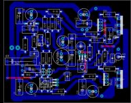
destroyer X said:
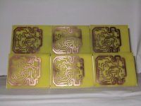
This image shows the more standard one..... The BC556 and BC557.
This is where the pictures of everyone's boards can become very confusing, I know I've had to check and double check and draw a picture and have a coffee and check again - lol, very confusing. For the record and any passing strangers, I'm using 2N5401 transistors for Q1 and Q2.
- Status
- Not open for further replies.
- Home
- Amplifiers
- Solid State
- Destroyer x Amplifier...Dx amp...my amplifier