Re: More well come constructors....less welcome modifiers
Any way. I placed a simple question and i don't had an answeer. Finally what is your suggestion. There is or there is not the need of an input terminating resistor?
Regards
Fotios
destroyer X said:
But i have friends that knows what i am telling all forum folks now, and they perceived, once more, the strange question...too much obvious to fótios, as he is deeply experienced.
- "Everybody is free to connect any input terminating resistor into
the input terminals, for source loading purposes... the Dx Amp.
is a general purpose amplifier, and it will work either HS or SS
source equipment"
Carlos
Any way. I placed a simple question and i don't had an answeer. Finally what is your suggestion. There is or there is not the need of an input terminating resistor?
Regards
Fotios

Dx amplifier sound fine, and can make all type of guys happy
To the ones that love "snake legs" or "snake oil"....mine personal, customised unit, are filled with some.
I do not like empty spaces or holes...as i have not binding posts, no multiturns trimpot and some parts where excluded from the design....i prefere to fill those empty spaces.
And kidding, as i am with a very special good mood today.
Ahahahahahha.
regards,
Carlos
Attachments
Here is your answer Mr. Fótios
"Everybody is free to connect any input terminating resistor into
the input terminals, for source loading purposes... the Dx Amp.
is a general purpose amplifier, and it will work either HS or SS
source equipment"
The volume trimpot or volume potenciometer will behave as a termination too, and can be used.
regards,
Carlos
Hi Fotios,
You wrote >>
Carlos i have a legitimate querry. In this schematic, it does not appears an input terminating resistor. I mean that, before anything else in circuit. Have you attached some outboard input potentiometer?<<
I don't see how you can expect Carlos to answer this question.
He has provided a general purpose power amplifier schematic.
Carlos cannot know what way any user would wish to use the Dx thereafter.
Some folks use a volume control. Some folks use a pre-amp. Some folks use a line driver. Some folks use as a slave from the output of another amplifier. Some folks drive from an I-pod or portable CD. Some folks drive from a DAC or computer interface.
Yours might seem a simple question, but it cannot be answered be a universal statement, so if I were Carlos I could only answer by asking you - surely it is the case that the choice is yours, and whether you want to use your own line terminating resistor is up to you alone, as indeed it is with the majority of power amplifier designs ?
Cheers ......... Graham.
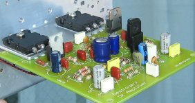
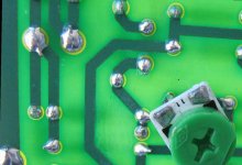
Some strange parts you may find, are parts used to fill empty places, or....
to cover binding post holes..... i use under wires, not to be seen.
Under the board you have the off set trimpot also, the wires that connect VBE and zobel filter grounding wire.
Everything, speaker, supply and input wires goes under the board....also the VBe multiplier wiring (twisted to create capacitance to couple colector with emitter) goes running under the board.
regards,
Carlos
Attachments
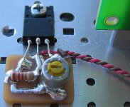
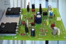
You will see the VBe multiplier board at left....
placed there only to show you...it will move to under the board, will be attached to the heatsink but under the board....not to be watched...it has to colect heat, not to be observed.
The input is not "shorted" by a 27 picofarads ceramic capacitor..it is there only to fill the empty holes.... this value will not work, exception will be the presence of 100 Megahertz and upper frequencies that will be tuned by this capacitor and the inductances present in the circuit.... well... will not pass to next filtering..so...do not worry and be happy.
Also i have not a broadcasting station in this building.... none "enormous" signal to bother us.
regards,
Carlos
Attachments
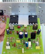
Well...this last view shows the VBe multiplier.
It is there, visible, for demonstration, to show up purposes only...it will disappear from my vision and very soon.
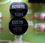
Why those "balls" of solder into the output transistors?
- because this same transistor, this same unit, was used in many schematics...normally they do not stay fixed for long time...soon will be removed to other circuit beeing tested.... new ones will take the removed one's place as this amplifier will be stand still...assembled for ever.
Cutted leads in transistors are a need to increase mechanical resistance... bending they broke into long term holding, and sometimes the leads break directly above the plastic base...this will kill the transistor.
The way i use, have thinner wires soldered, telephone wires; if something has to be broken, while bending , will be not be the transistor leads....will broke the weakest part... my thin wires will broke during continuous handle and bending...this way, transistor will be safe against damage.
regards,
Carlos
It is there, visible, for demonstration, to show up purposes only...it will disappear from my vision and very soon.
Why those "balls" of solder into the output transistors?
- because this same transistor, this same unit, was used in many schematics...normally they do not stay fixed for long time...soon will be removed to other circuit beeing tested.... new ones will take the removed one's place as this amplifier will be stand still...assembled for ever.
Cutted leads in transistors are a need to increase mechanical resistance... bending they broke into long term holding, and sometimes the leads break directly above the plastic base...this will kill the transistor.
The way i use, have thinner wires soldered, telephone wires; if something has to be broken, while bending , will be not be the transistor leads....will broke the weakest part... my thin wires will broke during continuous handle and bending...this way, transistor will be safe against damage.
regards,
Carlos
Attachments
Re: Here is your answer Mr. Fótios
Not misunderstanding me for all what I write. And me also i have made such omission. If you look at the drawing of Dirty Harry that I have sent to you and been also published in diyaudio forum you will see that in input is absent a terminating resistor; and because in the base of input transistor there is a resistor – after dc blocking capacitor – of 18KÙ to ground, somebody had asked me if it is the input impedance of amplifier. Immediately I hurried to clarify apologizing that there is a potentiometer in input of 50KÙ which don’t appears in the schematic and if does not want it somebody should be soldered a 47KÙ resistor in his place. This is my philosophy, does not want I leave in his luck each one. How many you believe that they have your own experience so that they conceive it alone them?
Regards
Fotios
I will explain to you why i maked this question. First of all, i did not deal never with DX amplifier and the reason it is obvious as I have published my circuit of Dirty Harry in diyaudio forum in that appears evidently my designing philosophy. I will report also the conflict that had burst out in thread boraomega and in which I was mixed without bad intentions, as I tried to help mr. Sakis Petropoulos. I point out again that beyond certain telephone discussions, no other relation I do not have with Sakis and us it separates a distance of 700 Km. Also nor my work has relation with the work of Sakis as i draw and I only try my own models of audio electronics while he is not a designer, simple he takes ready drawings of other persons and manufactures these. The difference between me and Sakis is enormous. I request you Carlos don’t mix me with Sakis again. The same I had asked from boraomega and I believe that he it respected. Fotios is a lone investigator for many years and did not decide suddenly puts partners in his work. It does not need therefore I say more in order to become comprehensible. And now in our theme. Because I receive personal e-mails (and not only via diyaudio forum but also through my personal web page) from persons that tried the construction of DX and have problems (as Sakis with Bora) in order to I do not appear rude against them – as I did not answer in no one because i am not interested to comment the work of other persons and simply I look to make rightly mine – because they increased somehow last them, I decided to look at the circuit of DX. Immediately my eyes was nailed in the input where was absent the terminating resistor. Because i don’t like only theories but I seat very long times in my workbench I remembered a bad experience that I had in the past with my Dirty Harry. When tried it alone I had always connected between his input and the output of my generator a potentiometer of 50KÙ and observing input – output with oscilloscope all they showed well. After this I constructed an auxiliary limiter circuit for the particular amplifier. By alone this circuit it showed good performance in oscilloscope. However when connected this circuit in the input of amplifier its output danced hip-hop. I tried hard for one week and in the end brought to despair I abandoned the limiter circuit. As however it happens always when we calm down certain days then we remembered who detail it slipped from us. Therefore in my own case the problem was owed in that I had removed the potentiometer of input of amplifier and had connected directly the output of limiter directly with the dc blocking capacitor of the input of amplifier (something such wants to say above AndrewT). Immediately I maked the following test. I removed the potentiometer from the input of amplifier and connected directly it to the generator. And in this case the output of generator began to dance hip - hop. Consequently it was not a blame of limiter. I connected again the limiter with the amplifier but this time I put also a resistor of 10KÙ between input and gnd and before the dc blocking capacitor. The problem was resolved, all goes fine from then and simultaneously i took also a good lesson. In whichever he has an oscilloscope and a dummy load I propose the following test to be confirmed what I write. Connect in the output of amplifier the dummy load in parallel with a small capacitor MKT 2,2mF and inject a square wave of 10KHz in his input, so that the output of amplifier swings about 10Vpp. Observe with oscilloscope the waveform before and after the output inductor –if there is one – and not only you believe me, but you will occupy also the work that it makes the inductor in the practice.destroyer X said:
"Everybody is free to connect any input terminating resistor into
the input terminals, for source loading purposes... the Dx Amp.
is a general purpose amplifier, and it will work either HS or SS
source equipment"
The volume trimpot or volume potenciometer will behave as a termination too, and can be used.
regards,
Carlos
Not misunderstanding me for all what I write. And me also i have made such omission. If you look at the drawing of Dirty Harry that I have sent to you and been also published in diyaudio forum you will see that in input is absent a terminating resistor; and because in the base of input transistor there is a resistor – after dc blocking capacitor – of 18KÙ to ground, somebody had asked me if it is the input impedance of amplifier. Immediately I hurried to clarify apologizing that there is a potentiometer in input of 50KÙ which don’t appears in the schematic and if does not want it somebody should be soldered a 47KÙ resistor in his place. This is my philosophy, does not want I leave in his luck each one. How many you believe that they have your own experience so that they conceive it alone them?
Regards
Fotios
Hi Fotios,
Just because you cured a generator / amplifier interaction problem with your Dirty Harry, does not mean you should assume that all other amplifiers need the same input resistance, which appears to be the basis for your question to Carlos.
Tube amps can have inputs upwards of 100k.
Signal generators should be stable - no matter what load is connected. Older types were also designed for calibrated output into a specific load, eg. 600 ohms.
You might have effected a cure for this particular example of instability, but you do not appear to have found, or explained, the actual cause.
Cheers ........... Graham.
Hi GrahamGraham Maynard said:Hi Fotios,
Just because you cured a generator / amplifier interaction problem with your Dirty Harry, does not mean you should assume that all other amplifiers need the same input resistance, which appears to be the basis for your question to Carlos.
Tube amps can have inputs upwards of 100k.
Signal generators should be stable - no matter what load is connected. Older types were also designed for calibrated output into a specific load, eg. 600 ohms.
You might have effected a cure for this particular example of instability, but you do not appear to have found, or explained, the actual cause.
Cheers ........... Graham.
Can you make the test that i propossed above? And after we can discuss again for the capacitive loading of any component. Because the loading is complex. If it is more resistive all goes fine. If it is more capacitive?? Or complettely capacitive??
And the observation of reactions needs square waves and oscilloscope because it is not easily audible.
Fotios
What I had to say I said. Also so much years where I deal with audio components from as long as I remember all without exception the constructors they have terminated all inputs of preamplifiers and amplifiers with resistors and potentiometers to gnd. And in most cases the value of these resistors referred as the input impedance.
Regards to all
Fotios
Regards to all
Fotios
Hi fotios,
Your approach is one of ;-
"there is a problem to guard against with the Dx amplifier"
Carlos' amp does not have the high internal gain and phase shift which can lead to other designs needing specific controls to keep them from becoming unstable.
We do not need to discuss anything about Carlos' amplifier.
In general all power amplifiers should be driven by a low impedance source, and anyone using the Dx Amplifier within an audio system is most likely to do so, and therefore will be unlikely to encounter the problems you suggest.
Cheers ........... Graham.
Dx amplifier has no problems...was hardly tested...problems can happen because of
human mistakes.... errors of constructor's decisions.
One possible problem could be the heatsink size...fast i have changed to diodes and VBe multiplier, as i have perceived people not experienced to conclude "what heatsink size would be good enougth"
The amplifier was tested several times....i have made 13 included this one i have made today...others made it too....it works.
Fótios.... i think will be good to say that people that goes to you, to find solution into Dx amplifier, may have some brain problems...people lost the North.... as you have nothing related Dx amplifier..... also i am in stand by mode to help everyone.... so...going to the wrong person shows that those folks may have some screw loosen inside the thinking machinery.
The person more adequated to receive questions about Dx amplifier, to receive complains about Dx amplifier, to find solutions to problems are here...named Destroyer X.....the ones gone to you, Mr. fótios...maybe have some problem.... say... a much bigger problem than an amplifier problem.... they are finding help in the wrong place.
Also you have sent them to me, and they did not have appeared here....no news of those complaining guys in my mail box or in this thread... at least they did not have explained me that had contact with you fótios.
Well...you are disconnected from Sakis...it is all rigth to me.... with the exception of Bora's chapter, i think Sakis is a very interesting person.
This thread was not made to theorical discussions Fótios.... please, open a thread to invite all theorical guys to discuss your unstability problem...but please, let Dx amplifier out of that...include your own experiences and open that to discussions.
If someone face those kind of problems with dx amplifier, ask them to come here to publish that, to show the Dx circuit constructed by them... i will be able to check if the construction is a real Dx amplifier.
You will have hundreds of folks to discuss with you, in your high Enginneer level...this thread is too much small to you....this is a constructors thread.... more to beginners than to scientists.
I hope we have communicated, and that we can finish our "ping pong" of conversations, in special related "unstabilities", as this is something i have NOT found in my amplifier.
Be happy fótios
Carlos
To be finished
In my last post i express also my desire for release me from other tiring and without meaning discussions. In conclusion everyone has his own right. I said that many times before. Good luck Carlos in your effort. And i am there always to help me or to help you.
Friendly regards
Fotios
In my last post i express also my desire for release me from other tiring and without meaning discussions. In conclusion everyone has his own right. I said that many times before. Good luck Carlos in your effort. And i am there always to help me or to help you.
Friendly regards
Fotios


- Status
- Not open for further replies.
- Home
- Amplifiers
- Solid State
- Destroyer x Amplifier...Dx amp...my amplifier