Thanks to all for the help with the spade terminals. They're shown on Mouser's page 1217.
Hi Carlos, thanks for the parts substitutions and I'll get the dimensions you asked for when I get home tonight.
The transformer may be the limiting factor. It had 1.6A fuses on the + and - DC rails. When it was operating in the receiver, it was putting out + and - 42 vdc at idle. Feel free to correct my maths, Mr. Ohm's law of P=I^2*R gives me 1.6^2*8 or about 20 watts into 8 ohms just before the fuses blow.
BillH, the formula you use would apply to a speaker-protection fuse, assuming a constant signal at the output of the amplifier and an 8 ohms resistive load.
Assuming a 10% voltage-drop of the transformer at full power, the maximum continuous power the transformer delivers at the amplifier-circuit is 1.6 * 38 * 2 = 121,6 watts before blowing fuses.
But in practice you don't play continuous sinewaves, also those fuses will not blow at 1.61 A current-draw
It gives you a ballpark-value of the va-rating of the transformer imo.
Best regards,
Klaas
The Dx amplifier will need around 2.3A to each rail...and for a single channel
Also considering losses...your DC supply will go down to 36 volts.
Under that condition, the supply fuses, feeding only one channel, had to be 2.5A each rail
Using a single supply for 2 Dx amplifiers, the rail fuses installed into the supply output, had to be 5A each one of them.
Your supply will be enougth to only a channel.
Better to find another second transformer, as this one will be enougth to a single channel...and even for a single channel it will be not perfect.
regards,
Carlos
.......................................................................................................
Thanks Klaas...i had a little different numbers, but your idea is fine too....mine was a little more abusive to the transformer.
BillH has transformer, and also output transistors, and those parts will fit only one channel.
And this makes sense to fast evaluation..Dx amplifier will produce twice the power...so.... that small transformer will hold a half of Dx amplifier.....so....not a stereo..only a single board.
regards,
Carlos
Re. amp amp
Yep, DestroyerX, I have seen your post criticizing my amp. In this instance you are right. But my amp didn't get burned like amazon forest but it distort at high volume. I'm going around in search of a scheme to provide more base current for my exhausting outputs.
regard,
Yep, DestroyerX, I have seen your post criticizing my amp. In this instance you are right. But my amp didn't get burned like amazon forest but it distort at high volume. I'm going around in search of a scheme to provide more base current for my exhausting outputs.
regard,
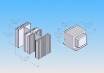
Yes Bill, they seems to be 200 watts components...not only the transformer, but also
the heatsink..... They will be enougth of one channel only...of course you can reduce your volume...but this will be hard to control all time long.
The heatsink, using a good fan, will work fine dissipating the heat of both channels i think....but even this way, your power transistor junctions may melt, as heat transference may not be fast enougth...the outside cooling may not help.
That 80W of each transistor is under 25 degrées centigrades...and that temperature, to be stable, is very difficult to control outside a laboratory that use cooling gazes and infinite metal blocks.
A very nice sketch....the image you draw Bill,...please, inform the program you have used to produce that nice image.
regards,
Carlos
.....................................................................................................
Dear Phung
It is normal that amplifiers, the ones has not protection to distort, to scream alike a crazy pig when over driven.
You may need a lot of power, not to force your unit into maximum clipping levels...as to perceive some increasing in power you need to double....to be clear the human perception of volume increasings, will be needed to multiply your power by four.
A good idea is to create more efficiency...more speakers, serial and parallel arrangements to increase sonic air pressure...more are of compressing air will result in more sound (more diafragm, speaker cone area).
Another good idea is to create a reflective wall around...as open air sound works need much more power than an inside walls system...because of reflections.
100 speakers, each one receiving 1 watt each one is many times better than a 100 watts speaker receiving 100 watts.
Also you can use horns...into bass speakers, and into mids and high frequency drivers...using acoustic amplification.
The exponential front grille is excelent for this purpose...in the speaker forum you will have many options.
In your sittuation, your needs, high power levels without distort, you may need something alike Linx amplifier... search for Delta Audio....Jan Dupont or even Jens Rasmussem may suggest you a high power amplifier enougth to your needs.
I have in my imaginations that an amplifier using 120 volts plus and 120 volts minus supply..... 16 to 20 amperes going to each channel may be reasonable for you.... i do not know if this is possible in your country.....no problems here, to find those units...from 220 to 120 Volts AC to industrial step down purposes...those ones, with a Variac in the primary is used into very high power needs.
I am not too much experienced with high power, as my needs do not go over 10 RMS clean watts each channel...normally my listening level is under 1 Watt.
The Symassym you are searching will not be enougth.... even Linx will need modifications to your use, as you may need 1 Kw or more, to play loud 400 or 500 watts RMS without distortion.
For sure, a cheap amplifier, a simple amplifier, will not match your superior power needs.... to you needs, Dx amplifier may be one of the worst options to use.
We are trying to keep our Amazon untouched, but there are many International interests there...people are burning there alike other countries have already made.... they were not perfect...we are not perfect too.
There are many Non Government Institutions working there to "save" the forest...in reality they are providing exportations of wood, some animals and plants to outside country.
I believe you have enormous jungle too....maybe your place will be more controled, as your people have shown us how decided you are.
regards,
Carlos
Yes..... will be interesting, the Thunderstorm X
Inspired into the crazy scientist.... already passed...dead, Ludwig Von Melter.
Do you want to make this one dear Graham?
To adapt Dx amplifier in such a way?
Your cooperation will be received as a party here.
The new monster, the melter...Thunderstorm X..the voice coils assassine... it is serious..wanna make it Graham?.... to 1 ohm voice coil..hehe...nice that!
Phong will burn Hanoi city wires and transformers.
I have made a simulation, and 2 Kw was not difficult over 2 ohms...a lot of transistors, bridged and enormous power transformers.
regards,
ahahahha
Carlos
Hi Carlos,
I was just looking through the "substitute transistor" list and was wondering about the input transistors. With the standard rail voltage of plus and minus 35 volts, which transistors are suitable.
Is Vceo > rail voltage the criteria?
Does your simulation show the actual voltage across c and e of Q1 and Q2?
Thanks
Emitters are near zero volt...and colector is -36 Vdc
Yes...Vce bigger than the rail will be enougth...better beeing twice the rail...to enter linear region.
So.... the transistor will hold a rail voltage, not from rail to rail.
Vce max beeing under that voltage will work fine there... the one that hold all voltage swing is the voltage amplifier.
The current swing in those input ones is very small..and voltage is also very small there.... as a consequence, power is small too.
The rail voltage more half the voltage swing (1.2 volts) will fit... (read Eva)
I think that all transistor suggested will work fine, and many of those were tested in my prototype....no problems Greg.
Selecting transistors that can hold twice the voltage you will have in your circuit, probably will fit, as the linear region use to be not so far away related half of max Vce.
Gain is very important for those ones...but even beeing this way..i could have very good results replacing 400 of gain to 120 of gain... even the colector load did not need adjustment.
Have you found something strange?.... go ahead....
Read Eva.... "Eva es la mejor"
http://www.diyaudio.com/forums/showthread.php?postid=539931#post539931
regards,
Carlos
Attachments
Re: Emitters are near zero volt...and colector is -36 Vdc
Thanks Carlos,
No I haven't found anything. I was just looking at the wide range of Vceo in the substitute list and noting the lead orientation. Some will fit the same way as the 2N5401, some rotated and other will need 2 of their leads twisted.
regards
destroyer X said:Have you found something strange?.... go ahead....
Thanks Carlos,
No I haven't found anything. I was just looking at the wide range of Vceo in the substitute list and noting the lead orientation. Some will fit the same way as the 2N5401, some rotated and other will need 2 of their leads twisted.
regards
re. more power
Hi carlos,
I think I have the point then, I will use bi-amp in this instance. I have 2 (max 300W) woofers in a cabinet then, I will use one amp for each woofer. That make 4 100w rated amp. 2 smaller amp for the (max 120W) mids and (max55w)tweeters.
But can I press more on your X design. Increase a little bit more. I'm thinking of reduce the overall gain in exchange some more base current for the output, sure a buffer preamp is needed. If you can show me the way.
regard,
No..i am not experienced related the mods you want.
Dx amplifier is cheap and simple....also it is already done.
modifications you should make may be under your own risk.
Try Symassym high powered version...or the Linx...they are very good and powerfull too.... and Linx has room to obtain much more power.
regards,
Carlos
Dx amplifier is cheap and simple....also it is already done.
modifications you should make may be under your own risk.
Try Symassym high powered version...or the Linx...they are very good and powerfull too.... and Linx has room to obtain much more power.
regards,
Carlos
OK Charlie, last help before we start the fire....
I now have the board mounted, insulated and thermal pasted...
60w lightbulb in series with live wire from mains....
wire harness connected
short connected over intput
3 multimeters with homemade crocodile clip wires...(was way cheap and I can kick myself for not haveing made em before... All you need is a 4mm regular banana plug, the clip and a piece of wire...perfect for low voltage work....)
10R 10W resistors installed in stead of fuses - only connected on amp side, so I can first measure check PSU section voltages... (did mini check with 9v battery last night, seemed fine).
Then I will solder the other lead of the resistor in place.
Install voltmeter on 2V range over the resistors
hide behind pillow, and switch on, then
a.) look for something to extinguish fire with ... eyes cat.
b.) see a voltage in range in the DMM
wait 10 seconds
adjust 10k pot until voltage on V+ rail resistor reads +- 0.5V
SHOULD OFFSET DMM BE CONNECTED ALL THE TIME?
adjust offset to 3mv
readjust 10k pot
adjust offset etc. until stable....
Does this sound right?
Hi Nordic,
It seems like Carlos is having a day off.
Are you following the "Adjust the bias, and trimming DC offset" instructions found here: http://users.tpg.com.au/users/gerskine/dxamp/
To quote step 11.
"Adjust the bias (VR2) to between 800 and 1,100 millivolts (0,8 and 1,1 volts) on each rail. Remember the positive rail will read slightly higher (about 100 millivolts) than the negative rail."
Please let me know if the instructions are not clear, so I can amend them.
regards
Hi greg, I have the other PCB type if you remember so I suppose it has minor setup diffirences... won't 1V over 10ohms give me 100mA bias? I thought Carlos said to go for 50mA....
PS. is it ok to have output DC DMM from the start or should I wait till biasing is set up innitialy?
PS. is it ok to have output DC DMM from the start or should I wait till biasing is set up innitialy?
- Status
- Not open for further replies.
- Home
- Amplifiers
- Solid State
- Destroyer x Amplifier...Dx amp...my amplifier