Yep R7 and R8 !
Be glad you don't go to this guy's dentist.... at least he has an ipod.
Be glad you don't go to this guy's dentist.... at least he has an ipod.
An externally hosted image should be here but it was not working when we last tested it.
Yeah, and a gun too !
This guy's dentist will think twice before doing a painfull rootcanal on him.
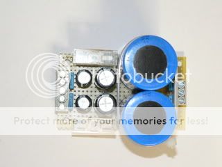
Well, since i'll have to wait for 2 psu-caps i've ordered,
for now i decided to do some p2p.
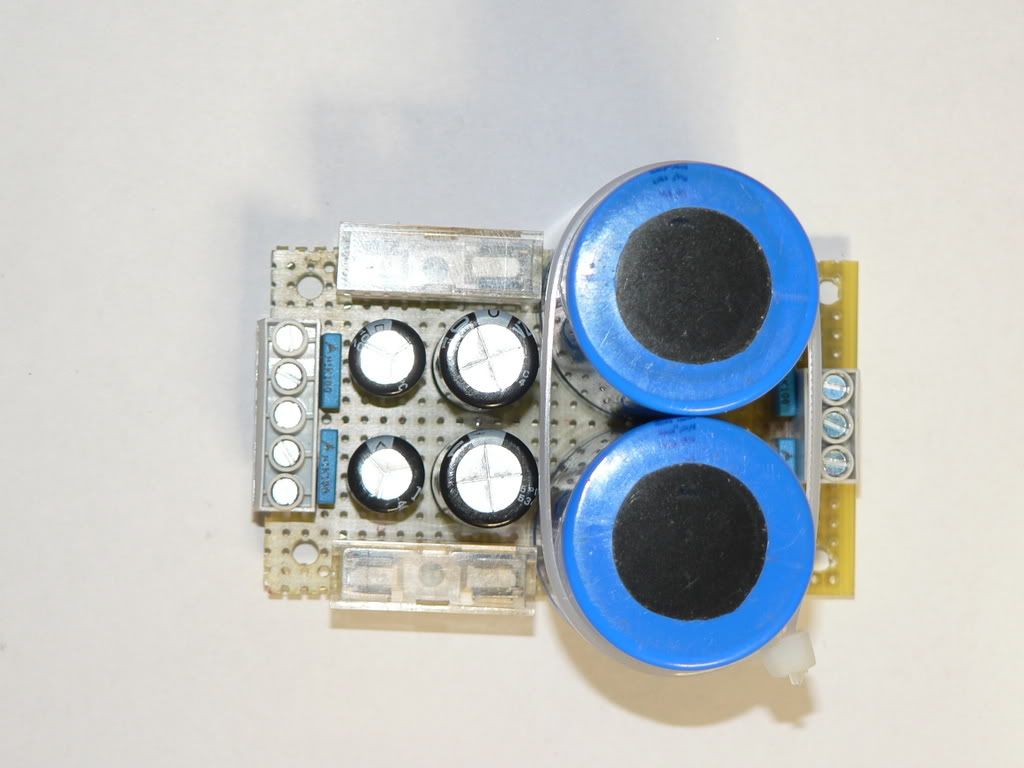
Top:
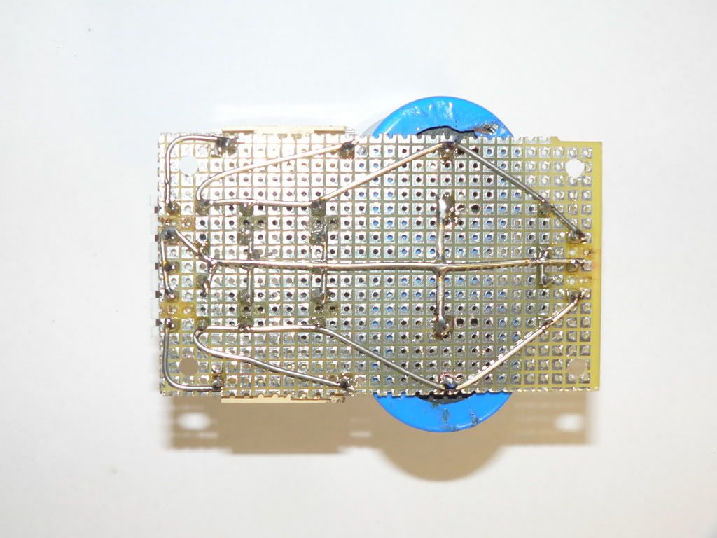
bottom:
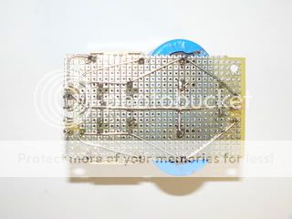
caps are 2x100nF/2x10.000uF/2x1000uF/2x220uF/2x100nF
Best regards,
Klaas
This guy's dentist will think twice before doing a painfull rootcanal on him.
Well, since i'll have to wait for 2 psu-caps i've ordered,
for now i decided to do some p2p.
Top:
bottom:
caps are 2x100nF/2x10.000uF/2x1000uF/2x220uF/2x100nF
Best regards,
Klaas
It is all rigth, also resulted pretty.
Those P2P remember my young moments, when was very easy to find those boards in my country.
Looks pretty, and enougth for the amplifier, beeing small enougth.
Will two audio boards, this supply board and the transformer fit inside the case you have?
Find, in your job, 1 to 2 milimeters thick steel plate to install between your transformer and the audio board...as beeing so near it may transfer mains noise....electromagnetic pulses will be captured into your wires and will be transfered to the audio circuit.
This way, some low level hum can be there, together your nice sonics.
Transformer can be magnetically shielded this way...using steel..not the inoxidable steel...nor aluminium
If you decide by a toroidal transformer, your problem will be smaller.
regards,
Carlos
Attachments
Will two audio boards, this supply board and the transformer fit inside the case you have?
Yes Carlos, but it will be a tight fit.
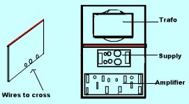
Without the transformer it looks like this - i added a printout of the stereo amplifier-pcb for illustration
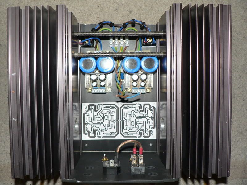
The transformer goes on top of this, it's essentially
a 2-story building.
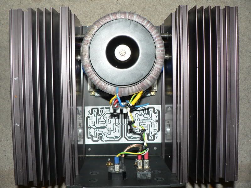
Transformer and mains input-wiring go on top, rectifiers, caps and amplifier sit at the bottom.
This way i also make use of the vertical distance, hopefully this will keep me out of trouble.
If this configuration causes audible hum
i can get upto 4 mm steelplate ,
if i bend it in an angle it could go under and behind the toroid.
best regards,
klaas
In the past I have put the entire power supply under the floor boards, brought DC up using cooker cable, and fitted just one pair of high value rail capacitors at the amplifier, which was no more than one little ali box with heatsink behind each loudspeaker.
Worked very well and hardly noticeable. All cables were under the floorboards too; just modified a couple of wall electrical boxes and drilled blanking plates to suit.
Cheers ......... Graham.
Worked very well and hardly noticeable. All cables were under the floorboards too; just modified a couple of wall electrical boxes and drilled blanking plates to suit.
Cheers ......... Graham.

Nordic said:Yep R7 and R8 !
Be glad you don't go to this guy's dentist.... at least he has an ipod.
An externally hosted image should be here but it was not working when we last tested it.
WHAT THE F$*(&* IS THIS !?


How is the DX amp progress ? How much power it can deliver ?
Symasym topic seems to be dead

Best Regards !
(I'll have a nightmare with this picture)
Not Wednesday yet can't wait to get the trannies, although there was a mixup with the doctors appointment and that is now tommorrow at 10, hopefully I feel good enough after, to go pick them up.,
It is a Mursi....The Mursi women are famous for wearing plates in their lower lips. These lip discs are made of clay. Girls are pierced at the age of 15 or 16.
The Mursi (or Murzu) are a nomadic cattle herder ethnic group located in Ethiopia, close to the Sudanese border. The estimated population of the Mursi is 6 to 10,000. Which is pretty much what you can expect if you want to walk about like that...
In your neck of the woods, the Suya indians from Brasil also wear lip disks...
http://www.leslietaylor.net/gallery/indian/1Suya-1.jpg
and the Kayapo
http://www.leslietaylor.net/gallery/indian/1Kayapo-14.jpg
Caiapo people is beautifull.... removing the botoques, those wooden pieces they use
to enlarge mouth, they are very pretty folks...that one is a nigthmare, remembers me Nazi propaganda before second world war....well, some native people from Africa make this exactly to look bad and to scare enemies..so...the dressing is working fine....but do not even try to kiss them..ahahaha.
Try to see Caiapós young girls....hummmmm...teenagers around 17 years old...they have beautifull faces, also others, alike Carajás and Ianomani.
We have millions...we did not exterminate our indians...at least they survived the first Europeans that arrived....they were not baptised, so, considered not humans during hundred years beeing this way ... what an ignorance we had in ancient times.
Nice cultural things..thanks Nordic....also thanks Nando because of the comments..... return to the begining of the thead dear Nando, explain all that thing agains sclucks...ahahahahha, cannot use other word...try to imagine was what slucks.... um peinte nos meus bells
.....................................................................................................
Thank you dear Klass..... very nice construction.... very holland one....really form Nederlands.....i cannot forget the Philips comes from Eidhoven, holland...... your worries about corrective maintenance was fine.
I am sorry to say that you will not have maintenance to make in this amplifier...having 40 to 50 miliamps current during stand by mode..... no traces of AC signal in the output...not having small oscilations, not having fluctuating off set (unstabilities) or not producing shorts in the output unfused wires (if forget those fuses)...it will delay decades till you will need to open it...maybe to see if there are spiders or cucaroach inside..but not for failures.
You tried to kill it....you have used a 1000 watts hair drier (or 800 watts) and you could kill it!.... hard to kill, this is the Dx amplifier.
* "hard to kill"... Dx Corporation, Marketing Department files... title number E0029834747778328378467383/12
regards,
Carlos
Hi
I think I will try to do the Dx amplifier, what is the input sensitivity ? (I would use it with a passive preamp.)
Any TIP power output transistor that I can use to replace the 2SC5200 and 2SA1943 ?
I have some darlington TIP 142 and 147 power output transistors , I presume those will not work in the DX amp ?
And I did made power amps with TDA7294 and LM3886 , what are sonic differences betwen the Dx amplifier and those one chip amps ?
Thank
Gaetan
Make a good visit into this thread my friend, you will find all your answers already
posted...in the Greg's home page you will have other transistor options, there are one circuit posted using TIP142/147 too.
Give us the honor or your visit...than you will have no questions anymore.
Forum is very rich...has all informs someone may need, but we need time and patience to read it all.
I have readed all Solid State forum...all threads, including the ones i do not like the subject discussed....also the theorical threads that i dislike...i have made this twice and already started the third time, as i could find answers to all questions i had, and reading once more i am turning myself better in knowledge.
I use to suggest friends to read the entire thread....not too much to ask when i have readed the entire Solid State forum more than once..all threads, all posts, i could colect informs of all gênius, all bad educated folks, the most talking parrots, the provocators, the clever ones and almost everything forum could give me.
Incredible place this one...but we need, in advance, to listen a lot..to read a lot.
No University can provide all that knowledge..also you cannot listen, and receive personal answers from Gênius, famous designers and hardly experienced folks.
The only thing forum cannot provide is experience....for that we have to burn our hands, to let computer simulator rest in peace and to put our hands on the job.... forum is so clever that it's title is "Do it by Yourself"....as this is the most important thing, as no one can be experienced only reading theories...he will be a mobile enciclopedia only.
Dx amplifier is here, in the Greg's pages... transistor options are there...the amplifier with TIP is in this same thread...about those LM chips i can tell you that Dx amplifier sound very good..will not buy a figth against zillions of LM constructors...find the real thing by yourself...try it!
http://users.tpg.com.au/users/gerskine/dxamp/
regards,
Carlos
TIP141 and cousines are able to dissipate 100 to 125 watts.
This way...amplifiers that can produce more than 80 watts will be turn the use of those transistors very dangerous.
Dx amplifier, modified to work with those transistors, will be able to work only producing 50 watts, as it can produce much more power (distorted) and this will make the output transistors work near the maximum...if square, continuous, fully distorted clipping output signal was produced.
Also it is published as 125 watts, but when you put it to dissipate 80 watts you will perceive that 125 watts was something not precise as dissipation..hehe.
Dx amplifier, using 35 to 37 volts supplies....simetrical ones, will produce power enougth to melt those TIPs in a metter of seconds if you install a 4 ohms (nominal) impedance into the output...not able to work with 4 ohms using a single pair of darlingtons.
The internal arrangement of resistance you have inside darlington transistors, at least this one, is not very good to audio purposes, more adequated to fast switching purposes...because of that you cannot "adjust" the first transistors emitter resistance
to optmize VBE for both of them... result is a little distorted audio using very high and very low volume levels..working fine during average power work.
Of course you can use them in pairs...many pairs, and the gain is absolutelly the same, so, emitter resistances are not needed for them...if you wanna remove them, do it without fear, as you will not have tears.
Using them into DX, a better idea is to use smaller supply voltage... 30 Volts for instance...and do not worry about losses in power.... you have to double your power to perceive, and very hard to perceive increasings in power....clear will be if you multiply your power by 4...... this happens because of human perception...we cannot perceive....so....35 watts amplifier and 100 watts amplifier sounds almost the same...you perceive a little more punch into the bass area only....inverting the logics, or, reducing power, the effect will be be same.
Different than us, humans, the speaker can perceive any increase in power, that will be transformed in speaker diafragm movement (limited in the extremes, turning sinusoidal waves into square waves very easy) and also transformed by heat.
So...some increasings in power.... more 50 percent, more 80 percent... will be nothing to your ears...may kill your speaker of burn your output transistors.
regards,
Carlos
Here is the thread short cut to the TIP142 version.
http://www.diyaudio.com/forums/showthread.php?postid=1168423#post1168423
regards,
Carlos
http://www.diyaudio.com/forums/showthread.php?postid=1168423#post1168423
regards,
Carlos
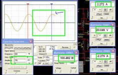
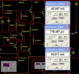
Here you have the off set and stand by current
Off set in the middle.
Positive rail current is in the top
Negative rail current in lower position.
Differences of stand by current are the result of positive rail zener diode that is receiving something around 10 miliamps of bias... this appears in the positive rail as the stabilizing circuit is using positive rail and ground only...of course could be made different...but was made this way...next amplifier(if this really happens) will have the same bias for both rails...and them everybody will feel more happy.
regards,
Carlos
Attachments
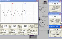
Here is an example, using darlingtons
Supply is 25 plus 25 volts.
Output power is 55 watts rms over 4 ohms
Condensers from Darlington bases to colectors are extremelly important..without them you will have oscilations and burns.
Simplified..extra small components count...zener suppressed...power on thump will be perceived clearly this way.
Bias will be small....5 to 10 miliamps each rail...off set smaller than 5 milivolts..audio quality is worst than normal Dx amplifier.
regards,
Carlos
Attachments
Here is the Dx grandson schematic..sorry, not pretty.
But also no one is constructing this one.
If someone appear as interested, i will provide him a better schematic, more clear, and less confused.
But this one....even confused, is working in the simulator...for sure this one will work real world, as i have made some of them in 2000.
Attention!...no way to work without darlington condensers...those ones form base to colector..do not even try..boooom! will be the result.
regards,
Carlos
Attachments
- Status
- Not open for further replies.
- Home
- Amplifiers
- Solid State
- Destroyer x Amplifier...Dx amp...my amplifier