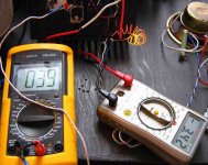
Sabotage was tried...the soldering iron tip touching the transistor top.
Heat was transfered from the screw to the transistor top, to the heatsink... and them to the junction...after 2 minutes a good ammount of stand by current was reduced.
The VBE multipler had acelerated his speed to control temperature increase.
regards,
Carlos
Heat was transfered from the screw to the transistor top, to the heatsink... and them to the junction...after 2 minutes a good ammount of stand by current was reduced.
The VBE multipler had acelerated his speed to control temperature increase.
regards,
Carlos
Attachments
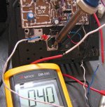
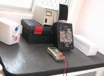
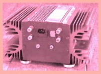
Those hard tests started with bias adjusted to 50 miliamps...amplifier cold.
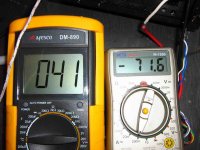
After testing with overdriven.... the current gone to 72 miliamps.
And the temperature never gone over 41 degrees celsius..this is a good human fever..not too hot for a power amplifier.
regards,
Carlos
After testing with overdriven.... the current gone to 72 miliamps.
And the temperature never gone over 41 degrees celsius..this is a good human fever..not too hot for a power amplifier.
regards,
Carlos
Attachments
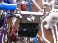
Modifications will be shown in those next two images.
Simple modifications..... a single resistance...the inclusion of the VBE multiplier that was tested with Bittner suggested values, and a new stand by current...more cold amplifier during stand by.. driver transistors works more cold now.
regards,
Carlos
Simple modifications..... a single resistance...the inclusion of the VBE multiplier that was tested with Bittner suggested values, and a new stand by current...more cold amplifier during stand by.. driver transistors works more cold now.
regards,
Carlos
Attachments
Nordic, my dear Nephew..you do not need to buy nothing...search for 2 resistances
with values that goes from 10 ohms to 150 ohms...no problem..they can be different...better if they are the same...less confusion.
Install those resistances in series with your rail wires..cut them and them install the resistances extremes into those two point you have now...as you have cutted the positive wire, for instance...... then, install a DC voltimeter....10 to 50 Volts DC may work
Voltimeter probe points will be: one at the resistance rigth side and other at the resistance left side...reading the voltage developed when the electrons cross that resistance...and applying ohms law..you will have your current reading
Do the same in the negative rails...with the other resistance...install a second meter there.
The voltage you obtain.... enter into a calculator machine.... expressed in volts..and them divide by your resistance expressed in ohms...the result will be the current entering...ohms law application only.
Fuse are other things...wire to give a guaranteed low resistance fuse is in the board...this is external related the board...not neede to install those things in the fuse place...unless you prefer this way.
regards,
Carlos
Yes..for the positive rail you can adjust 50 miliamperes.
The modified schematic will be posted in the Greg home page soon.
Also i will make something not so pretty to send you....send my your mail please.... i will make attachment for you..as the standard schematic use resistances...diodes and VBE multiplier are evolutions to the ones do not want to use big heatsinks and fan blowers.
panzertoo@yahoo.com
regards,
Carlos
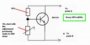
Here is the Vbe multiplier tested.
Worked fine.
The amplifier is standard using resistance and trimpot to create the needed bias voltage...made to be cheap, made to be simple, but need enormous heatsink and, or , fan blower to help cooling.
Other option, better to the ones that do not have big heatsinks is the use of three diodes and one trimpot to produce the bias voltage...those diodes must touch the heatsinks in a hot point.
The last option, to use small heatsinks, or to hard work, is to use the VBE multiplier...any NPN will fit....
Using VBE multiplier you will need to remove the resistances and diodes that were previously there....two wires will connect the transistor colector and VBE transistor emitter to the board, connections must be made in points marked A and C into the board you can see in the Greg's home page.
regards,
Carlos
Attachments
Negative...they are not giants..you will perceive that soon.
They are not more than the needed...and maybe you will need a fan....if you decide to listen at full volume for more than 10 minutes.
Watch the one i am using for a single channel hard driven.....
We have 30 degrees environment dear Nephew..this turns things hotter.
Do you wanna schematic Nordic?
I cannot publish it here, as the VBE multiplier is not the standard...the normal amplifier use enormous heatsinks, the father of your heatsink and resistances only.
The diode use is optional...also the small board to use VBE multiplier is optional too...for free, but optional...not included in the schematics.
I made a very special schematic, with the VBE multiplier, exclusive to you..will not be posted...but...to receive it, you have to send me a mail with your adress my dear.
You have not to complain dear nephew.... i am giving you a very special attention..all you heatsinks were calculated.... wanna to be shaved my Big Charlie?...ahahahahah
panzertoo@yahoo.com
regards,
Carlos
Carlos, that's kind of you. OK, something in return, for a gang of friends. You know each other via the forumand perhaps per email - why not phone each other? I stumbled onto http://jajah.com/ . It makes phoning a lot cheaper and members (membership costs you nothing) talk to each other for free! Bad luck for Nordic though, South Africa hasn't yet joined the club - but at their prices for international calls we can afford to ring him. OK, as soon as you have joined send me a mail with your number (and PLEASE your time zone), I'll mail you back with mine.
And PLEASE NOTE: I'm not with that firm, I'm not related to anyone who is - I just want to share something good I have found.
Greets to all of you,
Pit
And PLEASE NOTE: I'm not with that firm, I'm not related to anyone who is - I just want to share something good I have found.
Greets to all of you,
Pit
Negative Nordic..that 120 ohms resistance is connected between drivers emitters.
The VBE multiplier is connected into the drivers base..and before a small resistance.
Observe the schematic Nordic.... also go to the Gregs home page and you will understand watching the schematic.
When you use the VBE multiplier...that is an entire circuit, already having its own adjustment trimpot, will not need the trimpot you already have in the circuit.
So...if you decide to include the VBE multiplier you will need to remove the trimpot you have previously installed....if not removed, things will work in parallell and bias will not be easy to adjust.
please, send my a message to my mail, this way i will be able to send you some schematic, made customized for your.
Are you really not understanding your uncle Nordic?....hehe..maybe you are kidding with big Charlie...not good that in this moment...loosing time and i am a hell busy today.
But i love other kind of kiddings.
panzertoo@yahoo.com
regards,
Carlos
.........................................................................................................
Dear Pit...no way to use those things.....if you have 20 friends and go to the telephone...paying nothing or small money..you will be 1 hour with each one...the way i have made in the past....the day have only 24 hours....and people cannot stay talking because their own obligations...
In the past i have done.... was not good...i gave up to use those kind of communications.
Other thing that happens is that people turn shy in front of a microphone...Nordic will go under the bed!..ahahahaha.
regards,
Carlos
I suggested that Klaas check if oscillation was the problem by increasing the C.dom value to prevent it anyway.
I also asked about loudspeakers, and the fuses being used.
Klaas has e-mailed me directly, and maybe the problem is actually *mathematical*, not oscillation.
The speakers are very respectable DM7s.
The impedance shown on their STEADY SINE measured impedance graph is meaningless when being driven by music, because their momentary current draw will far exceed those for the impedances illustrated.
The fuses were 2A slow blow, but positioned *between the bridge rectifier and the rail capacitors*.
I would suggest 5A fast fuses between the capacitors and the amplifier, though two sets of fuses may be used.
Slow Blow or Time types between bridge and capacitor, but fast between capacitor and amplifier.
Indeed with the likes of a DM7, it is likely that 6.3 or 7.5 ampere rail fuses would be necessary, and parallel output devices.
So why do they blow only when the amp has been running for a while ?
Because hot transistors have a higher gain and can offer that little bit more drive and NFB control.
Some reviewers have observed that amplifiers need to be turned 'on' for a while before they sound 'best'; this is the reason !
It is also an aspect I make deliberate use of myself by having the VAS and drivers on an output heatsink to 'warm them up'.
Cheers .......... Graham.
I was thinking about those things too Graham..some of your thougths are mine too
In special the speaker impedance "valleys"...that deep in impedance depending the frequency.
I do not like the increase of the Miller one...it will destroy the sonic quality...i prefer if he can distribute capacitances in others transistors too... into drivers and output.... capacitors from base to colector or even small ones to ground...not increasing the Miller above 27 picofarads..as the oscilation may stop but audio quality in treble range will stop too.
Well...what to do...to relax..ahahahhaa...if needed to destroy quality in the name of stability.... decisions must be taken.
also i was thinking about his enclosure...also about high speed transistors....above you have my ideas... i am just trying to figure out what is going on there.
Klaas is using a very nice box...a case, enclosure...but it is made using aluminium plates..rectangular plates...the one is in the bottom, despite beeing aluminium, has not good convection cooling...because the top is covered by the top plate.... side aluminium are covered by heatsinks..so....side area do not work to cooling..only to damping, only to cooling delay...when aluminium absorbs heat for some seconds or minutes and you have a fake cooling.... when heated, has not the hability to transfer that heat to the air....as it is covered....
Convection cooling is a result of contact with the air.... heat is molecular movement...and this can be transfered to the air...as metals are swiming in the atmosferic air... the heat goes up...so...we cannot have nothing to block this movement...also heat going up, it suck air that is down....as a consequence we cannnot have nothing under..alike bottom plate having table ..with small distance because of short lengh of feet..not tall enougth..you need, at least 10 centimeters under things to allow convection colling...also at least 10 centimeters free over...and even with those 10 centimeters you will be on troubles, as will be convection cooling resistance.
Dear Klaas (he is fine....nice guy) have his enclosure frontal plate out of correct position...also the back plate...the only metal plate he has in his enclosure, working fine, is the top one...that one, alone, can hold 60 watts of heat....but others are not working fine....down one may be not more than 15 watts...side ones something around 30....the small frontal and back plates may allow 10 watts maximum each one....this way...i am afraid, that the enclosure, by itself....without the real heatsinks we have there, will not be able (without the heatsinks) to hold..... so.... not more than 135 watts (eye calculator)...the case can hold a 135 rms amplifier.
Dx amplifier, depending the speaker impedance valleys and peaks.... can dissipate 320 watts of heat..producing more than 200 watts of audio power.
Now let's make some examination in Klaas heatsinks..... observe they are not in the best cooling position.... there are resistances.... aluminium fins, despite having curves, are placed having other "stages" over...alike an appartment building...the upper stage will be a resistance to cooling....only the top ones will work fine....converting that complex design in something simple we will have 12 fins...each one having aprox. 25 by 8 centimeters...also the base will work....maybe 25 by 18....those measurements are made by eye... just a fast evaluation...this is not precise.... joining those fins areas with the base area we will have 280 watts for each one.... real amplifier watts.
But cooling position is not the rigth one...could be more than double if a fan blower was used to force air...... but this way....not more than half....this will result that Klaas entire case will hold around 400 watts of heat....... 320 watts will be needed to high power...and this is without oscilation...because going to oscilation, the supply power will be the limit..things can go over 500 watts.
This way...i think that Klaas is having oscilations triggered by signal...maybe...as i have not that magic cristal ball to see things.
Those oscilations are result of high speed devices "feeling" board capacitances and inductances...in the reality, those transistors are eagger to oscilate..they are potential oscilators.....every board has small capacitances from electrode to electrode..from copper rail to copper rail..as two metals near one each other will produce capacitor plates..also wires twisted one around the other.... also parallel wires...and capacitance is ratio of its length.... also inductances are found because of the copper line shape.... even beeing flat, you will have some capacitance...as really flat things do not really exist..only in our mind (a straigh line crossing USA will not be straigh... Universe is curved... so...the line will bent... globe is not flat)
When you have a capacitance associated to an inductance...beeing small...you will have a tuned circuit, add formula can calculate the resultant frequency....if the transistor is able to hold that frequency...ahahahaha...every signal entering will trigger the transistor into oscilations..dinamically trigered oscilations that will be together the audio....making the audio worst, forcing high power consumption and producing heat.
Those transistors, in my point of view, more a problem than a solution, need Miller capacitors or capacitors associated with series resistances...or even capacitors connected to ground to block that oscilation inverting phase and cancelling or having an enormous way to send high frequencies to ground...this way... charge and discharge cicles (the oscilation cicles) are beeing sent to earth as son as they start...they die very fast.
regards,
Carlos
Attachments
Wanna dream?... do you want that passion, that romance...emotion
Give to me the chance to show you the way...construct..even dirty and fast a Dx amplifier sample.
Listen to it and come to tell me if i am wrong.
The sound that will touch your heart...natural sonics.
Now, with pretty link to it.... nice colours there...detailed informations and three options of thermal compensation.
here is the button to fast jump to it.
http://users.tpg.com.au/users/gerskine/dxamp/
The Dx amplifier is the only one that will provide you an astounding sonics using JUNK.... search for the dirties, oldest, bad gain transistors you have...the worst capacitors..the ones with broken or short leads...old resistances...find a dirty awfull piece of wood....put nails on it... solder over nails and wire all the circuit.
Will kick a lot of amplifier you have listened!
Now Dx amplifier has "tripple guarantee".... reliability, sonics and life time.
Learn also.... to watch the beauty of an amplifier sonics...has no connection with pretty boards....sound is something we listen using ears...not eyes!
regards,
Carlos
")
- Status
- Not open for further replies.
- Home
- Amplifiers
- Solid State
- Destroyer x Amplifier...Dx amp...my amplifier