I know you are experience with computers, heat, overclocking and so on
But please...do not forget to install protective rail resistances....even those 20 ohms will fit...to avoid problems as bias may be too advanced, or off set too much out of the correct value.... start with the off set in the mid range position and adjust the bias one to minimum resistance.
regards,
Carlos
Attachments

What is the current entering that amplifier?
Yes..you already know that...as you are experienced Nordic..but there are young folks reading this thread...beginners as i was 40 years ago...and those simple things are "big help" for some of them.
regards,
Carlos
Yes..you already know that...as you are experienced Nordic..but there are young folks reading this thread...beginners as i was 40 years ago...and those simple things are "big help" for some of them.
regards,
Carlos
Attachments
Mydaugther Larissa, 10 years old, use to help me with my toys
She helped me to calculate this amplifier...that Dx amplifier..and she use to correct me...she already knows equation that i have teached to her.... and she do those things better than i can.
She knows how to calculate the entire amplifier...this topologie.
She is the main Dx corporation designer!....ahahahahha....can you believe....and it is true.
And there are folks pride because they know how to calculate resistances in parallel...my daugther makes more!
I want to present you my daugther.
regards,
Carlos
Attachments
She has not special..average intelligence and interests are normal for her age
But she loves to hold soldering iron with her daddy...and to understand the trails the electrons goes.
She use to revise my texts...to check my constructions searching for shorts and wrong connections..also she helped me when designing the Dx amplifier...she was the calculator operator.
More than my daugther...she is the chief of Dx Corporation Enginneering projects department...hehe
Just that.
regards,
Carlos
Attachments

Heh, Carlos handy, just got to keep her indoors for the next 60 years or so....
Hope you use real wood for the barbeque, I always laugh when I see people useing charcoal... yuck.
Is it better (less likely to blow up) to use the slower transistors - tip41?
I'm about halfway done putting the pcb and circuit in eagle... so far it looks consistant...
Hope you use real wood for the barbeque, I always laugh when I see people useing charcoal... yuck.
Is it better (less likely to blow up) to use the slower transistors - tip41?
I'm about halfway done putting the pcb and circuit in eagle... so far it looks consistant...
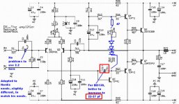
Here the last schematic, adapted to your needs Nordic
As the heatsinks are not so "enormous" as we hope, ....so.....the diodes will be helpfull to keep temperature under safe limits.
there's a fixed 47 ohms resistance...will be needed to reach the current, as 100 ohms alone is not enougth together those three diodes.
The VAS transistor, i think you will use a 200 Megahertz unit...the old and good BD139....but he may oscilate, as gain is good and it has that possibility, to oscilate in hi frequencies...better not to give it this chance including a capacitor (better Silver Mica....ceramics can work too) from 22 to 27 picofarads.
Those "radio frequency" transistors,...able to work till 200 Megahertz are eagger to oscilate...they need only to be biased and sensing the inductances and capacitances we have in our circuit boards they start to oscilate...the capacitances with inductances join together to construct a "tuned circuit"...and this will produce certain frequency of oscilation that are proportional to this capacitance and inductance....because of slew rate they are used...but....hummmm..can be a problem.
The input do not need so big capacitor as 4.7uF...if you prefer, you can reduce it to 2.2uf or even sligthly lower without losses in the low end.
I hope this helps you.
regards,
Carlos
Attachments
No!..... TIP41 is not better...it is just more safe
Using small leads into the BD139...good pcboard..with small copper lines...small in length and not near one each other.... installing the Miller one....BD139 will be sligtly better in sonics....but that difference is a hell difficult to perceive.
TIP41 decision was because easy to find... good gain...over 100 normally.... price is low... dissipation of the To-220 case is nice...and to be more safe...just that.
You can use your BD139...Klaas have used and he like it.
So...was tested by me and by Klaas...will fit your needs.
I think BD139 is wonderfull transistor...almost so good as MJE340 and MJE350....they are cousins...also BC630 and BC649 are younger cousins...alike young kids...less power they can hold only.
Capacitances of BD139 are very good.... this transistor is a guaranteed of quality by itself..used since the seventies...good ones.
Also the differential input...if you use the PNP BD140.... will work fine too.
Sorry..i use charcoal and i fire it using liquid or Gel alcohol.... good smelling wood is not so easy to find...but in our future meeting we will use the wood you suggest...since it turns handy for us....barbecue receive only salt...big salt grains only....and the salt goes in the moment the meat goes to the fire...and then, after some minutes, it is removed shacking it.... the surface is fast toated to avoid too much losses of blood..this turns meat more tender.
regards,
Carlos
Try old wood form grapevines... I must say over the years it is getting a bit more expensive finding nice wood for a braai, our word for barbeque, it is a South African speciality... especialy lamb chops, which is hardly eaten in some parts of the world... weird....
I have a feeling I should go for tip41 etc... because I am too dumb still to deal with many variables.... I need to be very sure.
Like you said before it is uncertainty which make people abandon projects midway...
Very confusing signals when you say, use this part, but wait, it is more likely to go nuclear and blow up your house if you get it wrong.
Thanks for the tip on input cap, haveing a problem finding the right size in 4u7... have not checked the filter values, so will take your word for it...
Tonight I'd like to get the final BOM done, so that I can go shopping tommorrow...
Thanks for the patience auncle Charlie, the circuit above,
I am at the output stage now, of entering the board into eagle, and still no problems... used tip41, as it does not have all models... will have to check pin legs with whatever I use....
I can allready see BC640, would go exactly oposite from the way they are drawn on the board... for input stage... at least I can't get those 2 wrong....
TIP41 is hardly used to output...but dissipation is small...this amplifier would need
Two pairs...each one will need one emitter resistance.
Good idea is to go for the more safe decisions...and then...near future, you can tweak, and substitute here and there...to make your own experiences and to produce your own conclusions about those things.
Everything will be fine...just give it a triple check...you already found the first damn problem...those BC639 can produce errors because their leads position.
And you are finishing....make one board with new parts and the second one with used parts..... another Myth will go down...used, junk parts, work as new...and sounds absolutelly the same.
Life is wonderfull...each day we learn a little bit more..... and i use to read other forum folks...there are a lot of things i do not know and i go learning.... i am very happy as i could make my own...and sounding excelent..you will see that.
What was the chip amp you have made...if LM3875...hehe...Dx amplifier will eat it in the breakfast...easy...fast and LOL.
No!... they are not bad...the opposite, they are excelent..producing a nice work beeing so small and having so small distances between leads....problem there are the protections..they interfere with sonics.
regards,
Carlos
The Audiophile chipamp is realy good, but not as good as our friend Will Ward, who also posts here now and again, 's hybrid amp, when compared AB, however since I added the Pedja Rogic Buffer, and corrected some (of my) errors, I think it might be loooots closer... doesn't sound like GC at all because the LM3886 part is used as a current pump...
I also have a plain GC standing here I must still go install for someone... lol I should get more speakers and hold a party, got 3 working amps here....!!!!!!!
I will probably use the 2sc5200 and SA1943 for outputs... are their pins the same - except for size, as tip41... I am just busy checking your friend's PCB.. it is perfect but I have one question....
On bottom left (by input) is a 10r resistor to lift input ground... I Also next to it is C10.
On schematic C10 is connected to ground.... should the horizontal trace from input not be cut after the 10r resistor joint, and C10 be connected to ground?
regarding r20,r21
Carlos, a very silly and most likely unimportant question: r20 and r21 are rated at 4.7 ohms.. i cannot find metal film resistors of this value where i live. my options:
1. a ceramic 4.7 ohm resistor
2. two metal film 10 ohm resistors in parallel
3. simply a metal film 10 ohm resistor
which way to go?
as this is my first time constructing an amp i have many such questions") in regards to my progress: so far i've found all the needed semiconductors and most of the resistors.. the real problem is finding quality caps here.. once greg is finished with the new pcb layout, i will etch it.
in regards to my progress: so far i've found all the needed semiconductors and most of the resistors.. the real problem is finding quality caps here.. once greg is finished with the new pcb layout, i will etch it.
the discussions in this thread are proving useful.
thanks!
Max
Carlos, a very silly and most likely unimportant question: r20 and r21 are rated at 4.7 ohms.. i cannot find metal film resistors of this value where i live. my options:
1. a ceramic 4.7 ohm resistor
2. two metal film 10 ohm resistors in parallel
3. simply a metal film 10 ohm resistor
which way to go?
as this is my first time constructing an amp i have many such questions
in regards to my progress: so far i've found all the needed semiconductors and most of the resistors.. the real problem is finding quality caps here.. once greg is finished with the new pcb layout, i will etch it.the discussions in this thread are proving useful.
thanks!
Max
Those are stop resistors...and value is not critical..you can choose the ones you
have around...from 2 ohms to 22 ohms
Those low inductance ones are prefered..or..the non coiled ones.
Old ones used films making turns...coils..helical shape construction...those are the worst possible to audio applications.
I will see that board Nordic..... my dear Raj disappeared and he could answer this easy...i will have to understand the board first to conclude second.
regards,
Carlos
That lift ground you said was there to reduce noises...and you can join C10 to that
lifted ground...input ground will be over the 10 ohms resistor....you will have the base resistance, the input filter capacitor , C10 and the small capacitor that is parallel with it.
Output ground, rail condensers ground and Zobel ground are not lifted... there you may use the standard ground.
Also if you do not want that lift ground...just short that 10 ohms resistance, or, substitute with a jumper and everything will be fine....better to use the lift ground, but was not included in my schematic because the decision was to make it as simple as possible with the lowest parts count possible.
Raj board was not made using my "philosophie" ...let's say this way...but was his idea...his cooperation....another option...and good one, as you have used it as your choice...so...was something very usefull for us.
And old post you made Nordic, were showing Nacho Libre.... interesting movie...very funny... the Latine version of Superman
regards,
Carlos
.....................................................................................................
Vurquuz
those stop resistors are to stop oscilation as soon it starts...the RC combination will produce this effect of cancelation...not a critical value...use your 10 ohms that will work fine.... i think lower value will be better...but this is not so critical.
Image attached was because of Nordic...an old post he made..i forgot to comment his message...not for you this one Vurquuz
regards,
Carlos
Attachments

Good to see you will be building this amp, Nordic, soon i won't be a lonely pioneer
Carlos' advices are excellent, i have nothing to add to them right now.
Nordic, if you want you can mail me those Eagle-files so i can do a consistency-check.
Raj's boards look lovely, i will probably end up using these.
I like the main capacitors on the pcb, makes the amplifier much tidier, less wiring.
I changed ground-connection of local ps-caps from long pcb-traces to short wire, low end sounds much better now.
I could install big powersupply-caps now without negative effects.
Before low-end sounded 'resonating', this is gone now.
Gave the amp a workout on those old-fashioned, powerhungry b&w's. Sounds
Carlos, allready training next generation DestroyerX ,so 50 years from now we still have DestroyerX
Greetings,
Klaas
She will enter forum as "Blackwidow" in early future.
Good those experiences you have made Klaas....i will try your idea too.
Do not tell people...but i have perceived those ressoances...you can see them with steady 25 hertz tone....just watching speaker diafragm movement.
I could not remove this effect.......but as now you have solved with my deep thanks...i can say that i could not remove that defect.
Reason why i was avoiding to say that was a excelent amplifier.... i was telling it was a very good amplifier ...now promoted to "Excelence" because your researches.
You know...i was afraid that constructors, perceiving that small problem could be angry against me...good that you found the way...ground loop was the problem...reason why Graham was insisting into the star ground.....that is it folks...experience is experience...the solution was at our hands...and Graham was telling us that
Point to Graham.... many thanks to you Klaas...and i feel ligthweigth with this small bug removed.
I want to inform you all that RAJ is following the forum and he informed that his board has no errors...that people can trust and assemble.
Kvholio....Klaas....please, the sketch related your grounding techniques...please!
Here is RAJ board, revised and guaranteed.
regards,
Carlos
Attachments
- Status
- Not open for further replies.
- Home
- Amplifiers
- Solid State
- Destroyer x Amplifier...Dx amp...my amplifier