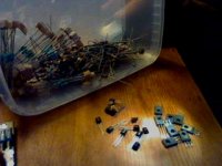
Next I found 8x BD139-10
Original Motorola goldleg, about 30years old
But used, so I need to find whether they are ok too
Also some unused BC547B, with goldprint and looks like Motorole or AA(?), also equally old
Also a couple of BC560B, goldleg Motorola, but used and old
Are these gems, or should be thrown away
I think I rember someone mention That those old Motorola to be really special
Lots of resistors I have to measure
Am I getting into trouble
Just be honest Carlos, should I quit these parts
Attachments
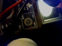
I also have this funny thing on my meter
Obviously fore testing something, NPN-PNP
But have no clew how it works
Is it of any use
Taj
Sounds good with your dad building violins
I have to be honest and say that have made one many years ago
And the one, not finished, that I showed to Carlos, I have been working on that for about 15years, or more
But it is an important part of me, and will always be
Im working on my house
Havent had a proper bathroom fore 5years, but close to get it done
After that I hope to get a dedicated room fore making some more violins, I wish
Actually I have all the needed wood fore a couple more
Nice old stored wood by now")
Should manage to get them done before I get too old
Obviously fore testing something, NPN-PNP
But have no clew how it works
Is it of any use
Taj
Sounds good with your dad building violins
I have to be honest and say that have made one many years ago
And the one, not finished, that I showed to Carlos, I have been working on that for about 15years, or more
But it is an important part of me, and will always be
Im working on my house
Havent had a proper bathroom fore 5years, but close to get it done
After that I hope to get a dedicated room fore making some more violins, I wish
Actually I have all the needed wood fore a couple more
Nice old stored wood by now
Should manage to get them done before I get too old
Attachments
DX LOGOS
That is too funny...
I still like the ones you posted first.
Yes indeed... personal taste is not a matter of discussion.
taj said:
Elephant logo huh? Okay, but I still think it's weird.
..Todd
That is too funny...
I still like the ones you posted first.
Yes indeed... personal taste is not a matter of discussion.
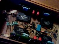
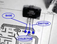
Oh...nice parts...those 2SC2922 and complementary are the best ones you can find
Also the other ones are nice parts.
Do not trow them out...or..trow them into my trash box.
heheheh.
regards,
Carlos
...........................................................................
Gaetan, from Canada, also produce violins.
Also the other ones are nice parts.
Do not trow them out...or..trow them into my trash box.
heheheh.
regards,
Carlos
...........................................................................
Gaetan, from Canada, also produce violins.
tinitus said:I also have this funny thing on my meter
Obviously fore testing something, NPN-PNP
But have no clew how it works.
Is it of any use?
Yes, it's helpful to tell you approximately what the current gain (hFE) of the small transistors is at some current level, so you can approximately match them. There should be a hFE position on your meter's main function switch.
Best use is for the input pair transistors (aka: the differential amplifier or Long Tail Pair). Those two transistors do their job best if they are matched.
The meter is not the best way to match them, but it's better than nothing. And assembling a better matching circuit is a pain the butt.
Insert a transistor ( using correct E, C and B pins - DX amp uses PNP (polarity) for the input pair), and the meter will tell you the hFE reading. Pick two transistors that have the closest reading.
Note: the heat from your fingers will REALLY screw up the readings. so try to use needle-nose pliers or tweezers to insert the transistors. If you must touch them, wait a long time for the reading to "cool down".
That process is really educational to demonstrate how sensitive transistors are to small temperature changes.
..Todd
Re: Oh...nice parts...those 2SC2922 and complementary are the best ones you can find
I may just do that
Its a pain to measure all those hundreds of non assorted resistors, and only find a few right ones
Maybe I just give in and order the needed parts
Thanks Taj
I will try that
I also have a file saved somewhere with instructions fore matching
Man, my eyes hurt and head is spinning, time to rest
destroyer X said:
Do not trow them out...or..trow them into my trash box.
heheheh.
I may just do that
Its a pain to measure all those hundreds of non assorted resistors, and only find a few right ones
Maybe I just give in and order the needed parts
Thanks Taj
I will try that
I also have a file saved somewhere with instructions fore matching
Man, my eyes hurt and head is spinning, time to rest
Attachments
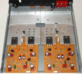
Hi Carlos
Finally my newly bought laser printer, HewlettPackard P5, old blackandwhite, got into use that makes sense
Actually I bought it mostly to make print of schematics, reading stuff etc
1. Any idea why the prints of boards ends up wrong size?
2. Also, is it common to mirror image bottom layer?
My Sankens seems to be shorted on all legs
3. If I buy new, is it ok to choose Sanken 2SC2922/2SA1216?
4. Could I use other drivers than TIP41/42, say TIP31C/32C?
5. Or maybe MJE340/350?
Attachments
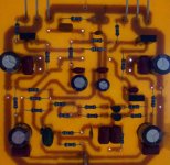
Thanks Carlos
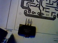
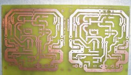
The reason I show picture of bottom layer was to show how much size is off, when I print it
Says that board should be 98mm long, but my print is 160mm
How can I fix this
Or I will need to draw the hole layout by hand
Prices are high on components
Will try look at digikey
Got nice F5 boards today, but thats a project fore colder days, only collecting components now, some fore DX also, and other projects
I have no postscripts Juergen.
So, dear Tinitus, if you do not know how to adjust your printer, them try simple calculations.
98 mm real size informed to printer resulted in 160 milimeters
X will be the size you gonna inform your printer to result 98mm
160X=98 multiplied by 98
160X= 9604
X= 9604 divided by 160
X= 60
So... while printing, inform 60 milimeters to your printer..do not inform the real dimension of 98 milimeters.
I will produce a pdf file...maybe this gonna help you.
Here the image in GIF
regards,
Carlos
Attachments
I will post some images that will help you.
An externally hosted image should be here but it was not working when we last tested it.
Attachments
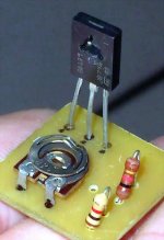
The VBE multiplier has two wires on it..one to the colector
and other to the VBE multiplier transistor emitter.
The colector wire goes to the board to point "A"
The emitter wire goes to the board to point "C"
regards,
Carlos
..........................................................................
Will be waiting forum reset, after 1 minute to post another image and message....aaagh!... this should be 10 seconds..not 60 seconds!
Attachments
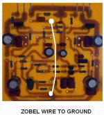
Zobel filter does not have copper line to ground
so you will need to run a wire from the zobel filter capacitor to the ground.
This was the result of many ideas about grounding... result that mess into ground...board can accept many options of grounding.
I am using Ground Grounded Earthed.....ahahahahah!...also terrestrian mudy , humid, with lame. sand and stones.
Means that the transformer secondary center tape is the ground..this same ground goes to speaker negative, goes to chassis , go to potentiometers metalic cases and goes to heatsink.... this is the main ground..also goes to the point in between the electrolitic condensers (ground)
the input ground is exclusive..connect there only the feedback condenser..and the copper line was already provided into the board for this purpose..and you will connect the input cable audio shield to this low noise input..the lifted ground between the first transistor base resistance and ground..the 10 ohms lifted ground point...ONLY TO INPUT SHIELD.
regards,
Carlos
Attachments
- Status
- Not open for further replies.
- Home
- Amplifiers
- Solid State
- Destroyer x Amplifier...Dx amp...my amplifier