To the VAS compensation, start with 150 picofarads.
It is more safe..with the treble boost "on"..the amplifier turns very sensitive....not so difficult to have oscilations...so.... try the 150pf and goes reducing.
Finding the bad value...when reducing.... increase the value found to a bigger one and check the amplifier for stability.
If it oscilates, or is unstable, just putting your finger into the input you will listen to broadcasting radio stations and nice noises of frequency beatings and some interesting noises.... well.... i love Radio frequency too.
regards
Carlos
Attachments
This one disturbs the bias adjustment, because it keep the voltage stable
You go adjusting and the condenser charged keep the voltage stable...this turns the reduction of bias slow in time... to increase no problem...but to decrease you have to wait.
Reduce it to a value smaller...2,2 uf or even lower.... but install there, at least, 100N
regards,
Carlos
You go adjusting and the condenser charged keep the voltage stable...this turns the reduction of bias slow in time... to increase no problem...but to decrease you have to wait.
Reduce it to a value smaller...2,2 uf or even lower.... but install there, at least, 100N
regards,
Carlos
Attachments
Here you see a suggested stand by current.
But really....better is to check if the output is conducting too.... measure over the emitter resistance.... if you are satisfied with the bias current and checked that the output is conducting, then fine!
regards,
Carlos
But really....better is to check if the output is conducting too.... measure over the emitter resistance.... if you are satisfied with the bias current and checked that the output is conducting, then fine!
regards,
Carlos
Attachments
You see the maximum continuous sinus output voltage over 4 ohms loads
Well, this increase a little when using 8 ohms loads.
But, in the reality, the High Resolution II was sacrificed into the power to obtain audio quality, to use rail regulators that reduces 5 volts.
Those volts, reduced, will reduce the output power, because the swing depends from these voltages.
The real power is around 35 watts RMS and 65 watts RMS, of course to 8 and 4 ohms.... the sound is great.... you really will not be missing the lost watts.
regards,
Carlos
Attachments
Yes... i know that people loves power...so...here a suggestion to modify to increase
The swing.
If you are using 37 volts or more... then use green led
If you are using 35 volts.... then use the red led.
With this led in series, you will increase the voltage, the zener voltage will be added by the led voltage....
This way you will reach 45 watts RMS over 8 ohms and around 80 to 85 over 4 ohms... this will be better..and will depends from your supply.
If your supply has more voltage...hehehe.... put 2 leds in series...those green ones!.
Because of the LEDs, to make them ligth on, the resistance was reduced to 330 ohms...observe the schematic.
regards,
Carlos
Attachments
If you decide to supress the rail regulators.
So... you see into the image, were i am showing you the input circuit current consumption during stand by mode.
The equivalent resistance that can substitute the upper rail regulator is around 500 ohms to the positive rail and a little bit smaller into the negative rail.
regards,
Carlos
So... you see into the image, were i am showing you the input circuit current consumption during stand by mode.
The equivalent resistance that can substitute the upper rail regulator is around 500 ohms to the positive rail and a little bit smaller into the negative rail.
regards,
Carlos
Attachments
You welcome Mongo...you know that i have strong appreciation over your person
I think you have a great mood!
Well... people can use other voltages, can supress the rail regulators if they want...also they can substitute the differential loading by resistances into the colectors.
Powerholics can go to 50 volts without any problem..have only to replace the electrolitic condensers to units that have bigger insulating voltage.
The resistance that feed current to the input differential zener voltage regulator will need replacement for a bigger one.... 3K9 may fit till 60 volts without problems.
The bootstrapp resistances will need power re-calculations if you decide to increase your voltage.
Your output transistors will need more units in parallel.... i have tested using 56.5 volts... and i perceive that we can use 2 pairs..if you go to bigger voltage and power...better to increase your transistor pairs into the output.
The stand by current will increase a little.... force all output transistors to conduct using your bias adjustment trimpot...measure over the emitter resistances.... 3 milivolts over the 0.22 ohms resistances will be, already, more than 10 miliamps circulating into the pair you will measuring... so...increase a little the emitter resistance when using more pairs into the output... 0.33 ohms will be good.... and 1 to 2 milivolts over those resistances will be fine.
In this case..your positive rail current will jump to near 100 miliamps using 3 output pairs.
You will need better transistors when crossing the 50 volts barrier.... use better transistors, the ones can hold 120 volts of more from colector to emitter.... seach for Dx Turbo into this same thread and you will have good suggestion of better transistors to use.
Going to 55 volts...you will need 3.5 amperes each rail... the transformer will be huge..also the power will be good.
1 pair, into the output..using 50 volts, is already dangerous...the top limit...cannot use 4 ohms in this case..very dangerous.
Increasing voltage, the condensers will need to be checked, the transistors will need replacement to bigger voltage units.
Be carefull...be happy.
regards,
Carlos
Good Nordic...you have adjusted to a preset value your trimpots to supply
Have you checked the resistance into your construction?
I have to check those things..so many amplifiers i have made (options) those last weeks that i cannot remember all presets i had.
regards,
Carlos
Have you checked the resistance into your construction?
I have to check those things..so many amplifiers i have made (options) those last weeks that i cannot remember all presets i had.
regards,
Carlos
Hi there!
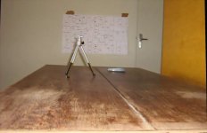
I've been building a DX Standard, last night I completed 1st channel; it worked great! (at least on the scope).
Will complete the amp this weekend -- photos will be posted. I am excited to hear music thru it, but will wait for stereo.
I am using MJ15022/15023 as output transistors, I have the Toshiba's but will keep them for the HRII that I will build when I have the PCBs. The rest of the circuit is to spec.
Wish me luck!
Beware! It will look ugly (prototype nailed to wood ), but I'm sure it will sound pretty.
Thanks Carlos for you design and sharing your knowledge and experience.
I may have questions.
I've been building a DX Standard, last night I completed 1st channel; it worked great! (at least on the scope).
Will complete the amp this weekend -- photos will be posted. I am excited to hear music thru it, but will wait for stereo.
I am using MJ15022/15023 as output transistors, I have the Toshiba's but will keep them for the HRII that I will build when I have the PCBs. The rest of the circuit is to spec.
Wish me luck!
Beware! It will look ugly (prototype nailed to wood
), but I'm sure it will sound pretty.Thanks Carlos for you design and sharing your knowledge and experience.
I may have questions.
caps
Carlos, thanks for the DC simulation with the network I proposed!
It shows that this network cannot be so easily applied and would need some more thought...
Hello Nico Ras, no, this is not a bass boost!
If you look at the details of the numbers and assume that the base of Q2 is a really high impedance input like the negative input of an ideal Opamp, then the network I have drawn has a constant voltage divide ratio versus frequency. Only the impedance of the network changes with frequency. Okay, the values I have given ignore the input impedance of of Q2 and would need to be tweaked by help of simulation.
Andew, yes, I am aware that the sensitivity to temperature drift will increase...
I took the schematic of the DX amp mainly to show the concept of the proposal. Key point of the proposal is to avoid a large electrolytic cap with a network that can be realized using plastic caps. This comes at the expense of higher DC offset ... nothing is for free in this world.
Anyway - thanks for your thoughts!
-----------
konkret
Nogoodboyo...if you had the chance to know big fat charlie in a close way, you would
conclude that i prefer to watch those ugly constructions, i feel those things result of passion, people that made efforts to make something facing problems, as material problems...having not parts the one used junk... having not transistors.... using something he removed from old damaged appliances.
You know, i see those things with better eyes compared with normal constructors.... i see strange amateurs ordering professional boards, using Eagle and talking about small specifications details that ears cannot listen.... i see those things in a very strange way.... alike entering a hospital with crazy folks saying:
- "What are you watching?... don't you know that I am Napoleón Bonaparte? "
I see those things as non natural..... not really pure DIY...not really amateur...i feel as those folks are professionals frustrated, non suceeded into real world and landed into DIY to prove themselves they can make so good, or even better, than professional....so.... a little sick people.
I would be very happy to see the mess.... the spider.... the dirty assemble...real, truth, amateur...to see the passion...the need to make...the need to listen...this is much more important to me.
Yes.... i tried to make good boards....in the reality Greg made...klaas made.... RAJ made..... Nico made (Nordic).... and others, as Ecat and some other folks too......but this is to be good to more guys, to have more and more people enjoying Dx amplifier, i cannot see those ones, that need professional boards as "pure" diyers, the way i can see diy is the more simple way...constructing over a piece of wood.... soldering over copper nails or something more creative.
I would be very happy to see your construction.... and with a good image...i wanna see all the mess.... to share your passion... this will make me more happy...believe me that this will be this way.
I am at your service.... everything you want can count on me.... within my knowledge limits i will help you... go to my direct mail and ask everything you want... you will have fast answer.
panzertoo@yahoo.com
regards,
Carlos
......................................................................................................
Konkret
I have just give up to tweak.... your off set can be corrected adjusting resistances.... so.... this is not the problem.
You idea did not have failed.... i have just simulated the way you suggested and observed that need tweaks only.... fine tuning only.
I will try, into the near future, your idea into my prototype, and them it will be corrected, adjusted and listened.
Off set is not a problem, it is adjustable..... but if will be stable or not, i will see during the experimentations.
I promiss that you will have return about this subject, in this thread...but you will have to wait...i have some ideas to try and things to do inside my home.... have to paint things, to fix things here, to construct some furnitures, to create an air flow system to my home to use the wind air pressure, to create dimensioned air ducts inside home, opening windows into the wall...well.... i need some creative job here.... i am thinking how to create coloured smoke to watch the smoke travelling inside the appartment... to understand the dinamics here.... were are the problems here... wind not flowing correctly inside my home...there are pressure external entering...i could see with a helical toy...made of paper... flowing and blocked when entering the appartment..so...need to create exits to start the air current inside home.
regards,
Carlos
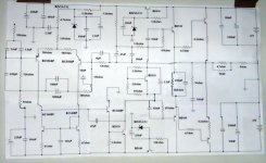
This is the High Resolution II schematic that i have
I hope not wrong or different from the one you have.
So many things happened that some modifications could be missed, or included into my schematic and not included into yours.
regards,
Carlos
I hope not wrong or different from the one you have.
So many things happened that some modifications could be missed, or included into my schematic and not included into yours.
regards,
Carlos
Attachments
I will try Nordic... despite that i am awfull with computers
My daugther tried to make a chart.
I told Graham had more than 100 years old...ahahahaha.
She felt pitty and made a chart....result not good...but.... she was nice to make.
I will upload you a 300K image dear Graham.... i hope you will read the correct numbers despite your 101 years old.
regards,
Carlos
Attachments
She asked me how grandfather bread (Graham) can drive?
Bread because Graham is a bread in my country... those dark bread that has seeds on it...we use this bread a lot here.
I told her, as a answer, that Graham when perceive some transit sign, he stops the car, walk to the sign, and very near, 20 inches distant he read..and them he enter the car once more..ahahahaha.
Kidding with her..... of course, latter i will tell the truth to her.
She is lovely.... she worried about Grandfather bread.
Nice girl...lovely.
regards,
Carlos
Attachments
- Status
- Not open for further replies.
- Home
- Amplifiers
- Solid State
- Destroyer x Amplifier...Dx amp...my amplifier