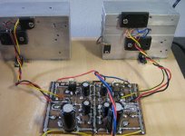
The supply board, electronic part, is ready
Ready to start the challenge to make it work.
The boards, made using my ancient method.... pen drawing.... well... result is disgusting.
I have made some retouches to show you the idea.... the real board is very ugly.... 5 times worst than this one shown
regards,
Carlos
Ready to start the challenge to make it work.
The boards, made using my ancient method.... pen drawing.... well... result is disgusting.
I have made some retouches to show you the idea.... the real board is very ugly.... 5 times worst than this one shown
regards,
Carlos
Attachments
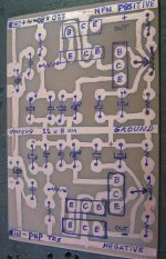
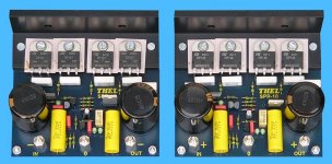
Here is the board... sorry.... very ugly.. i feel ashamed
But.... at least i am informing all the steps.
I have marked the parts over the board, i hope you can understand... also the board size is written there.
This way, when ready, and tested, i will produce an image having this one as a part of the entire image, and will place the values around with arrows pointing to the places were the parts go.
I see... the PNP power transistor, into down position.... into the negative board regulator side... will not fit the power transistor to be mounted directly into the board.... will need wires.
Well... some small bugs to face.
The circuit will be tested... if result fine, then i will fix that detail and some others that may appear.
regards,
Carlos
Attachments
Hi Nordic,
While Carlos' board is cooking - did you say something about what you are hearing with a series output 0.22 ohm resistor ?
Some amplifier-loudspeaker combinations sound even better like this, because it prevents loudspeaker circuit 'Q' from causing high series resonant current peaks.
Cheers .......... Graham.
Graham Maynard said:While Carlos' board is cooking...
I think the heatsinks will need to be massive to drop from 45 volts to 17 volts at 3.5 x 2 amps. I think the only real practical way to make a fully adjustable linear PSU is to use an autotransformer infront of a 70 or 80 volt PSU.
regards
Yes.... if you have a 55 volts supply, and adjust it to 45 volts.
And suck 3 amperes from the supply, while adjusted to 45 Volts, the heat will be very big.
Over the transistor, from colector to emitter, the worst sittuation is that the supply will hold the 55 Volts.... but this do not happens in the reality..... if happened this way, 10 volts from colector to emitter multiplied by the current crossing will represent 30 watts of heat to each rail.... total will be 60 watts.
But... in the reality, the transformers, or supplies having rectifiers and condensers, when drained with a lot of current... alike 3 amperes each rail, normally loose a lot of volts.... the more common is to go from 55 to 47 volts.
Under this sittuation.... the colector will have 47 volts and the emitter 45 volts because your output adjustment made....only two volts from colector to emitter, transistor conducting into maximum.... saturated... really "on".... under this sittuation, a very common sittuation, the power over the transistor will be small... 2 volts multiplied by 3 amperes will result into 6 watts only.
So... the most you drive... the best will be related heat when having those supplies... the stabilizer input voltage (comes from the transformer, rectifier and filters) going down aill reduce your heat problem.
You may ask... and what will hold the power?
The transformer will supply the power and will be hot because of that... the circuit, the amplifier will produce consumption of power, and because of that will produce sound and will be hot too.
The supply will keep voltage stable and will provide capacitance multiplier to the output... the effect of beta multiplied by the electrolitic condenser.
Of course... if you have a 55 Volts supply... the one huge that can keep voltage stable into the filters... and you reduce to 17 volts and drain a lot of amperes... the heat will be awfull...so... not a good condition to use electronic regulator this way...better to find a lower voltage transformer.
In the special sittuation , where we have a huge supply.... that kind of supply you suck 3 amperes and the voltage goes down only 3 volts!...well.. this one do not need an electronic stabilizer.
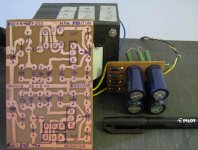
Attached the supply i will construct very soon.... for sure will work fine, i have to test is my bad transformer, if will provide conditions to the stabilizer to work... my transformer is loosing a lot of volts when hardly drained (loaded)... i will see if this circuit will hold the job... cannot make miracles.... will not be possible to keep 45 volts into the output when the input voltage reduce to lower voltage than that.
regards,
Carlos
And suck 3 amperes from the supply, while adjusted to 45 Volts, the heat will be very big.
Over the transistor, from colector to emitter, the worst sittuation is that the supply will hold the 55 Volts.... but this do not happens in the reality..... if happened this way, 10 volts from colector to emitter multiplied by the current crossing will represent 30 watts of heat to each rail.... total will be 60 watts.
But... in the reality, the transformers, or supplies having rectifiers and condensers, when drained with a lot of current... alike 3 amperes each rail, normally loose a lot of volts.... the more common is to go from 55 to 47 volts.
Under this sittuation.... the colector will have 47 volts and the emitter 45 volts because your output adjustment made....only two volts from colector to emitter, transistor conducting into maximum.... saturated... really "on".... under this sittuation, a very common sittuation, the power over the transistor will be small... 2 volts multiplied by 3 amperes will result into 6 watts only.
So... the most you drive... the best will be related heat when having those supplies... the stabilizer input voltage (comes from the transformer, rectifier and filters) going down aill reduce your heat problem.
You may ask... and what will hold the power?
The transformer will supply the power and will be hot because of that... the circuit, the amplifier will produce consumption of power, and because of that will produce sound and will be hot too.
The supply will keep voltage stable and will provide capacitance multiplier to the output... the effect of beta multiplied by the electrolitic condenser.
Of course... if you have a 55 Volts supply... the one huge that can keep voltage stable into the filters... and you reduce to 17 volts and drain a lot of amperes... the heat will be awfull...so... not a good condition to use electronic regulator this way...better to find a lower voltage transformer.
In the special sittuation , where we have a huge supply.... that kind of supply you suck 3 amperes and the voltage goes down only 3 volts!...well.. this one do not need an electronic stabilizer.
Attached the supply i will construct very soon.... for sure will work fine, i have to test is my bad transformer, if will provide conditions to the stabilizer to work... my transformer is loosing a lot of volts when hardly drained (loaded)... i will see if this circuit will hold the job... cannot make miracles.... will not be possible to keep 45 volts into the output when the input voltage reduce to lower voltage than that.
regards,
Carlos
Attachments
Looks like I've missed lots here today, two tutorials in fact !
I do like your boards Carlos, no drilling (yay !) and you can see both the components and the tracks. Given these benefits I don't think you should worry if the board does not look pretty.
Nice description of how to do voltage regulators, this could be very useful.
Power for the input stage: regulate main supply or use a separate supply ? I like the idea of the separate supply but I know nothing of the technicalities
You know about remote controls dear Ecat, and of course other things related your
profession and special skills.
We are complementary in this life, and because of that we need one each other.
Also you are humble, your tests made, in the past, show clearly to me that you have a very good know how.
The board, the way i use since 1969, give me this special help, we can follow the tracks watching the board... the circuit is there, clear to be watched... this helps a lot.
regards,
Carlos
....................................................................................................
Nordic
You have made a question... about what audio i prefer.
I feel more satisfied when using the rail regulators.... i feel them better than electrolitic condensers related sound... the rail regulator, that capacitance multiplier results good in sonics to my ears.
Also avoid enormous condenser.... really, i think they make the circuit board very ugly... and they are expensive too.
Alike Ecat, i think the best idea is to use double supply, or double winding secondary transformers... or to wind some turns of wire over some transformer you already have to produce another output (extra) having 7 volts AC more.... then, you can use a regulator that will loose around 5 volts from colector to emitter, and even this way will supply more 4 to 5 volts to feed the input.
Those double winding transformers or to construct the second winding over the original winding you already have.... need only to solder two insulated wires into the original output and produce some turns around the core (sometimes we have space for that)...just that.
Other option is a small transformer... very small, but able to give you the voltage needed... higher than the output voltage, and the regulator will take care to adjust the voltage to your needs...also you can substitute the zener by a trimpot and adjust the voltage.... you can turn it adjustable too.
Despite i love this idea.... not new... very old idea... in our forum Jan Dupont is using this idea since 2003 i think... or even before that.... despite my appreciation, i think it is a "complication"... one more problem to face.... and this is not a very good idea to DIY... as we need things "executable".
Sounds better with rail regulators, rail electronic stabilizers... but the way i am using is not the better one... we are reducing the voltage to the input, when we would increase it.
A sacrifice to make it simple and cheap...but not the better idea.
regards,
Carlos
Or you could go mad like me and use multiplier and large caps...
After Graham convinced me to try large caps on the output pairs, you will have to pull them from my boards over my dead body... Sure, they'll set you back anything from $5 - $20 upwards, but people blow that kind of money walking around the shop on a Saturday afternoon anyway. (I think it is just us pensioners who feel the pinch somedays).
The addition of the large caps is even more important in the plain DX, wow what a diffirence it made there...
No problems...beeing happy.. go ahead with your whale condenser units..ahahahaha!
I have made a lot of things today... the Dx Precision today schematic, date october, 22 will be sent soon.
The supply was finished and tested
Here is the final schematic.
The heatsinks, one to each rail, is an aluminium blade, thickness bigger than 2 milimeters, square, measuring 13 centimeters each side.
The input voltage, from the supply, unregulated voltage is 56 volts...the adjusted output voltage is 50 volts.
The supply stabilized the output voltage under 5 percent when loaded both rails sucking 3 amperes.
To the amplifier, Dx Precision, the way it is now.... with not more than 190 watts RMS over 8 ohms... the supply is perfect... no milivolt variation... the 50 volts stays there..not matter you do with your volume knob!
The input leds have variations of intensity, because the voltage there variates...but the output ones do not change the ligth intensity, because there, no variation of voltage ocurr.
regards,
Carlos
Attachments
Supply is guaranteed....you can already construct if you want
Because you can adjust voltages, from 24 to 52V to each rail, having extremelly good stability and no noise (not low noise...it is No noise!).
Tested with 300 watts of consumption.
The supply has not overcurrent protection....no short circuit protection...so... have to use a 4 amperes fuse to each supply rail, to avoid problems.
The transistors are TIP41 and TIP42 for error amplifier and driver, and use a 2SC5200 and 2SA1943 to the output.
Zener will be 1 watt... even half watt will work fine.
Resistances are half watt or 1 watt.... condensers are for 63 Volts.
Do not worry and be happy... using the Dx Precision, full power over 4 ohms... around 190 watts RMS.... you will have around 6 amperes and 5 volts over the power transistors... say...into the supply output... this means 30 watts to each transistor... relax... the one will receive the heat will be the transformer.
regards,
Carlos
Attachments
Yesterday i felt something strange into the dinamics
Maybe this regulator is killing the amplifier dinamics.
I will try a switch... those HH ones... the switches used to old guitars.... also used to mains supply switch, the ones we have into the back panel to switch from 220 to 110 VAC.
I will try... it is interesting... the sonics are better, much more precise, the treble is more clear, the punch is better..but i was searching for the dinamics and i could not see where the one is hidden?
regards,
Carlos
Hello Carlos
I seen that kind of dynamic lost in some commercial amps using regulator, it's not an easy task to do a amp regulator, since a power amp regulator need to be faster than any big rapid transients that the amp will have to amplifie, or the amp can lost some dynamic.
But I don't know if it's the problem for this DX regulator.
Have a nice day
Gaetan
Just a thought Carlos,
In the past whenever I have used regulators in non-class-A audio, they have always been of shunt types.
These are very inefficient and give off most heat when the amp is running quietly, but they did a much better job of limiting rail voltage, and did not affect maximum power.
Also very simple - just a Zener in series with a power transistor base, and a very large heatsink.
Another thought that comes to mind if you want to increase and stabilise the suupply to the differential and VAS stages without using a separate transformer, is to use a capacitor+rectifier voltage multiplier - where the value of the capacitor is chosen to match say twice the current draw required.
Cheers ............. Graham.
Hi,
just guessing but I suspect lack of transient current into reactive load.
If output is 28Vpk (50W) into 8r0 then that is 3.5Apk.
But the 8ohm speaker with it's crossover can require upto 28/8/0.35=10Apk.
If the regulator can only supply 3Apk then it is not going to hold the supply rail stiff into reactive speaker loads.
The undersized regulator just not going to perform (=sound sux).
Yes.... thank you boys... good points.
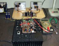
I have constructed a test set.
For a while, first listening tests... i could not perceive difference..will wait latter.
The sittuation, now, is 56.5 volts unregulated compared with 50 volts from the output stabilizer, the electronic stabilizer published some posts ago...take a look on it boys.
Not the rail regulator now..... now the problem is overall...total stabilization provided by a fast stabilizer that is controling excelent...no overflow into digital multimeters and no pointer shaking into analogic dc voltimeter.... sucking energy bigger than the amplifier the voltage loose 5 percent only... so... in the reality it is loosing 5 percent during peaks.... and 5 percent each rail.
This is the comparison.
Observe the sketch i have made.
Negative Andrew T.... into the rails, feeding small current... the simple rail regulator, the capacitance multiplier, zener referenced or feeded using series resistances with a condenser into the mid way from those resistances works fine...do not sux...suck current only...negative!
regards,
Carlos
Attachments
- Status
- Not open for further replies.
- Home
- Amplifiers
- Solid State
- Destroyer x Amplifier...Dx amp...my amplifier