Thank you Nordic and Dudainc.
The mail i have lost was because had transistors loosen inside the package.... a very heavy package i think, and X ray inspection found those transistors....they were big units from Sanken, my dear friend Klaas have sent to me.
The most safe way is to put only one board into an envelope... two sheets of paper around the board to create some kind of paper foam package.
The manual inspection will not block those kind of things.
I have not understood how Duda could help me while in São Paulo... also for Duda is not very safe to receive things from outside the country...but thank you anyway Duda.
Do not worry and be happy..... one board is easier than two boards to arrive...but also two boards, depending the size will arrive, as i have received a lot of boards from RAJ.... from Malaysia.
Do not write more things than the adress over the envelope...everything different will be reason to be blocked to inspection..and them the bureaucracy will start.... if you say have not value..they will block to watch if really has no value.
This country is a little bit different.... the idea is not to make noise..do not call attention or paint things into the envelope..the most simple possible will work better.
Hugh Dean used to send me small parts inside an envelope that had air bubbles inside.... excelent this mail from Australia...i have never lost his parts... he sent me once small capacitors...and in other moment he sent me 4 pairs of special matched drivers...i have never lost a mail from Australia.
I remember that a very old friend from New York had sent me a Sony Receiver.... without the transformer to reduce weigth, and partially dismounted..... that friend paid more than 30 dollares.... the package came by ship to brazil...old thing inside..... 2 monthes latter he received the package back into his home in New York.... written over was the information that was a non regular importation!... in the reality was more junk than a receiver...very old and without parts...more than 25 years old!
The customs officer spent other 30 dollares to send the package back.... so..... the clever customs prefered to spend money from brazilian government.
My friend lost his 30 dollares... i have lost the dismounted receiver and brazilian government has lost 30 dollares to sent the package back...only losses...very stupid those things.
Rent the DVD with the movie, The Terminal, with Tom Hanks and Catherine Zeta Jones and you will see how stupid can be bureaucracy.
The adress ... i think you have dear Nordic.
thank you in advance.
regards,
Carlos
destroyer X said:
...
I have not understood how Duda could help me while in São Paulo... also for Duda is not very safe to receive things from outside the country...but thank you anyway Duda.
...
Dear Carlos
What I offered to do (so you understand) is to take your boards (+components if applicable) with me to Brazil around December 18th.
After going through Customs in SP, I would go upstairs to the Agencia de Correios and would mail it to you using Cedex (with tracking).
I lived in Brazil until 20 years ago and I know the system well.
Since I visit the country often, I always carry goodies for my DIY friends.
This was never a problem since they never went overboard and asked me to take things like a double-door wide fridge or a 63-inch LCD HD display, etc. - you get my drift.
You seem to have a good solution regarding direct mailing, but please remember:
(a) anything below 50 USD does not pay duty;
(b) the total allowance does include the actual shipping;
(c) if a value is not declared, the inspection guys can get very creative... "been there, done that";
(d) comercial samples with declared values were never an issue.
I would rather deal with the mob than with the Brazilian Customs // Correios... I have not seen a change in the last 20 years!

Boa noite!
Perfect!.... deal made.
Thank you Duda.... very kind..... i will be waiting.... this way much more safe Duda.... and instruct me, please, how to return the money to you.... your Sedex from brazilian mails (internal fast system... 12 hours and ready into your hands)...as this will cost 12.50 shinning dollares (cost to Northeast till 2 pounds weigth inside card box)
Obrigado, valeu essa, foi muito gentil, bacana de sua parte.... eu sou uma criança grande.. vou ficar esperando... você vai ser o papai noel que vai trazer o meu presente!
So, dear nephew Nordic...mail it to Duda.... and thanks Nordic.
My adress:
Carlos Eugênio Mergulhão
Rua Dona Balbina Menelau 56 - 1601
Candeias - Jaboatão dos Guararapes
Pernambuco - Brazil
South America
54440 - 615
regards,
Carlos
......................................................................................................
Well..... advisers and couselors
I have understood clearly, i have readed with attention, and all fine.... Graham text understood in 80 percent..that swing of voltage was not clear to me.... the language is a problem into this sittuation...i need someone that can explain this in spanish, french or portuguese.
The VAS i am using is working fine into real world... the schematic i have sent you...i could not burn it unless when i force the amplifier to oscilate removing the compensation cap...that modified Miller effect one...Cdom......
The oscilation i had using long cable without shield plugged into the input... and them beautifull noises of RF modulation was listened...beautifull and full swing at the output.... i had burned BD139, the one used as master VAS (i call master the second one)
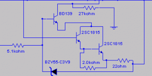
I made the same testing once again with the protection suggested by Graham.... using 33 ohms into the master transistor emitter, the one is generating the bias to the control transistor at your left (BC547).... worked fine.
Into stand by mode, this BC547 has 300 milivolts from base to emitter, so, it is not draining energy...not loading the circuit..only the colector to emiter capacitance (BC547) that creates some effect...not so big in the reality.
I will research a way to cancell this capacitance effect...maybe resistance, inductance ...i will do something there..for sure i will do...for sure.
I have received some suggestion from Mr. Danbury, and i will give a try on it too.
I have also send square waves, 5 volts square wave into the input...highly distortive signal was into the output resistance....an inductive resistance, wire wound resistance was used...and the circuit, this protective circuit Graham suggested, and that have Andrew T help into calculation, worked fine.
So, if nothing better appear into my mind or my hands of my mail box till December, i will use this one....people can disconect it using pads..into protection transistor base and colector, as suggested by Andrew T.
I am sorry dear Graham, i am so stupid that i really had some problems to understand your explanation...i could get 80 percent of it.... i also use meters into the transistors and also i use to try to overload them into simulator.... the master VAS is huge to its task i think... see the BD139 data..... not a very big current or big swing will cross it.... i really have not understood what have killed that one i had shorted... i am still surprised...and this proves that i have not a perfect understanding of this subject...well...i am someone that makes a lot of efforces, but i have some knowledge limits too....
Well, at least i can evaluate listening having good experience on that.... at least i have that to compensate the ignorance... and courage to expose myself without too much problems..not shy.
regards,
Carlos
......................................................................................................
Dear Ecat
My sweet baby is with me (my daugther Larissa), and will be with me this weekend.
Wife will come to cook something special, and to have lunch with me..now we are good friends....hummmm..... a little bit more than that.
ahahahaha
regards,
Carlos
Attachments
I will try this VAS someone sent me by mail
It seems has less capacitance...will see how it sounds.
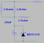
I do not like the huge resistance used... because of the big current selected to zener.
Of course, missed capacitor (into my own schematic attached) will be included and tuned
regards,
Carlos
It seems has less capacitance...will see how it sounds.
I do not like the huge resistance used... because of the big current selected to zener.
Of course, missed capacitor (into my own schematic attached) will be included and tuned
regards,
Carlos
Attachments
Hi Carlos,
Like you, I test amplifiers without screened input cable to see if they behave okay and do not oscillate when 'stray' signals get in along with the wanted audio.
33 ohms might be too high for VAS current limiting, but I don't know what your new VAS current is designed to be.
If the VAS current is 10mA then with 33 ohms its swing cannot be 10mA +/- 10mA.
The peak current before the current limit transistor starts conducting can only be 10mA + about 5mA = 15ma; and across 33 ohms this would make 495mV.
The limiter would be fully conducting before a VAS current of 20mA becomes possible.
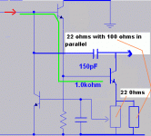
So for 10mA of steady VAS current a 22 ohm resistor will allow full +/-10mA alternation on transients, and the component value may be adjusted inversely with current.
Though 33 ohms would be fine with a VAS current of 6 to 7mA.
Cheers ......... Graham.
My VAS is having 11 miliamps into stand by mode.
Yeah...thanks...i will reduce to 22 or 24 ohms.
Do you think this will be a good value?
How many milivolts from base to emitter you think will be a good adjustment?.... say, to the protector transistor..the BC547
regards,
Carlos
Yeah...thanks...i will reduce to 22 or 24 ohms.
Do you think this will be a good value?
How many milivolts from base to emitter you think will be a good adjustment?.... say, to the protector transistor..the BC547
regards,
Carlos
Some people have asked what i use as pré amplifier
I use my digital system, from Philips, not old.... 4 to 5 years old i think, technology is very modern inside.
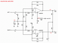
It is almost all digital, except the headphone amplifier, this one is analogue.
Because of that.... having not too much stages to mess with the sound, i have decided to use it.
regards,
Carlos
Attachments
After digital switching and step electronic volume control, the sound goes to the
headphone amplifier.... a good chip (not the best, but good) is used, simple circuit and using all regulated and stabilized supplies... high quality capacitors and condensers are used, shielded and having low output impedance..... to use 22 to 100 ohms headphones.
So.... beeing low impedance, has "power" to drive high impedance loads without too much problems as losses of signal level because of the load.... able to hold very low impedance loads, the unit works fine...need only a dummy load for it, to work happy and them go into the power amplifier..... level is less than one volt i think....enougth!
I think that avoiding stages, i will be avoiding problems...as each one of them can create me distortions, errors of phase....well.... bad sonics creations.
Yes... i do think that a good DAC and a discrete pré amplifier will be a better idea... i will ask my Croatian friend, owner of the Pulse factory of DAC and amplifiers, to send me one board for demonstrations purposes...ahahahahha... i am not sure will return the DAC for him...ahahahha..not sure.
regards,
Carlos
Attachments
Hi,
the protection for the VAS must allow full VAS variation to pass without limiting.
If you set the VAS quiescent current (bias) to 11mA then the full range of the VAS can be 11mA+-11mA (for symetrical signals). that is a range from 0mA to 22mA.
The protection transistor MUST NOT start to switch on at this range of currents. If it switches on earlier then it will be audible and fails the first test (sound quality).
The protection transistor starts to turn on @ about 400mVbe.
To allow 22mA to pass with <=400mVbe the base to emitter resistor must be less than 400/22=18r2.
Use 18r or 16r for the base to emitter resistor. Not 24r nor 22r.
The remainder of the degeneration resistance must be added back in as a second resistor feeding the VAS emitter.
That is why I keep repeating, you must split the degeneration resistor into Rupper and RLower.
If your earlier sound quality test was made with a 33r base to emitter resistor AND with VAS Ib=11mA, then the protection would turn on at very tiny input signals and is guaranteed to affect the sound quality. It would take a tiny swing of just +-1mA around an 11mA Ib to turns on the protection if it starts at 400mVbe. If it starts at 380mVbe then the available swing reduces to +-0.5mA compared to the required +-11mA for full output swing capability.
If the protection starts to turn on @ 370mV then the available swing is +-0.2mA. Hardly any signal at all. What if the VAS current increased slightly due to the mains voltage being slightly high during your test? The mains could easily change the VAS Ib by +-10%. That too should be allowed for in calculating WHEN the protection should start to activate.
DX HRII arriving for Xmas
What money? The lady at the Correios (SP) told me that she will send it for free since you have not charged any of us for your time or for the use of your designs.
 Tio Carlos - estou apenas retornando a gentileza. Se quiseres mais alguma coisa para rechear a caixa e completar as 2 libras, é só avisar. (Santa's helper)
In the meantime I will keep my fingers crossed for the success of the DX Precision.
Needless to say I am anxious to have Nordic's boards on my test bench...
I can even hear myself "expressing freely" after holding the soldering iron by the wrong end... (again)!

Have a great weekend everybody!
destroyer X said:...
and instruct me, please, how to return the money to you
...
What money? The lady at the Correios (SP) told me that she will send it for free since you have not charged any of us for your time or for the use of your designs.
destroyer X said:...
Obrigado, valeu essa, foi muito gentil, bacana de sua parte.... eu sou uma criança grande.. vou ficar esperando... você vai ser o papai noel que vai trazer o meu presente!
...
 Tio Carlos - estou apenas retornando a gentileza. Se quiseres mais alguma coisa para rechear a caixa e completar as 2 libras, é só avisar. (Santa's helper)
In the meantime I will keep my fingers crossed for the success of the DX Precision.
Needless to say I am anxious to have Nordic's boards on my test bench...
I can even hear myself "expressing freely" after holding the soldering iron by the wrong end... (again)!

Have a great weekend everybody!
Carlos has some very interesting audiotioners.
An externally hosted image should be here but it was not working when we last tested it.
Ahahaha...fine!...thank you Duda.
Put Mashmellow inside the box..ahahahaha..fine that!
Good!
regards,
Carlos
.......................................................................................
Thank you Andrew T.... was very clear...good teacher...very good teacher!
But, if you don't mind...i will use one resistance..to make it simple...i feel folks will not use that in the reality they will switch this off...but, as some of them have asked..will be included into the next board made... and will be for the Dx Precision i think.
Maybe Nordic will want to produce another set of boards... then he can include the protection if he want.... people can decide to install or not to install.
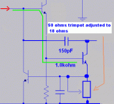
So... 18 ohms will be better.... will adjust to this value.... as i am using trimpot for a while.
It is sounding fine with 21.5 ohms (trimpot adjustment is hard).
Very good teacher...clear explanation...reduced your high technological way of speak to a level, that allow us, simple mortal, to understand..thank you.
Carlos
.....................................................................................................
Lovely picture dear nephew Nordic.
thank you
regards,
Carlos
Hi Destroyer,
The emitter resistance on the VAS should remain fixed. If you change the resistance on the emitter you are changing the degeneration and that changes the operating point and the gain of the VAS stage.
If you want to adjust the trigger point of the protection transistor you must tap into the middle (approximately) of the emitter resistor.
If the resistor is 500ohms, you could use a 500r pot and take the wiper to the protection transistor base. Not ideal since the wiper contact may not be as secure as a soldered joint.
But you need a much lower value of emitter resistor.
How low a value of pot do you have?
You could parallel a fixed resistor with a pot to give the correct degeneration resistor value that you need and then tap off the voltage to the base of the protection transistor.
But, best of all is the two fixed resistor method. The pot method allows adjustment of the trigger current and this may tell us something about when it becomes audible. Your first report may be correct - it is always audible! or maybe at some usable trigger value.
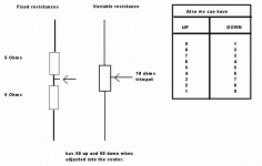
Stand the two resistors on end. Solder the flying ends together. Solder the other ends into the breadboard. Take the flying junction to the prot base.
I have used trimpot to testings only
Now, the 18 ohms resistance is already there..fixed and working fine.
I was using a trimpot (50 ohms) adjusted to 22 and them for 18 ohms because i had not found the 18 ohms fixed resistance..now it is there.
I will not use two resistances..only one.
But, by the way, a trimpot, adjusted to the mid point is the same as 2 resistances in series, having a tap into the middle.
Do not worry and be happy.
Now i am constructing a power regulator (stabilizer) to the supply.
Already have constructed 5 amplifiers, as options to compare and decide...now i will go to the supply...will return to the amplifier next week.
regards,
Carlos
Attachments
Yes... i understood latter your idea.... but really... i have perceived into our
forum that a lot of people dislike the use of trimpots.
Well... they are more usefull.. more flexible.... we can adjust and fine the "beat zero"..... of course when low power is used.... they do not hold power.
One trimpot, into practice, has the value of 10 or more resistance arrays
regards,
Carlos
Attachments
Hi Carlos,
I think your choice of an 18 ohm VAS emitter resistor will be just fine.
This is just enough to help linearise VAS operation as it swings between 0mA and 22mA limits. I don't think it should be audible, but of course you will be listening for this anyway.
Another trick for stabilizing VAS current when bootstrap resistors are used, (even better than using a CCS) is to parallel the bootstrap capacitor with a zener having a voltage close to that already appearing across the bootstrap capacitor during normally biased set-up, and then to halve the resistance of the upper bootstrap resistor by parallelling it with another component of the same value.
This is something I tried some years back but never saw published - and I clean forgot about it until today when I noticed it on one of my old sketches of a very low distortion circuit.
It is an arrangement which will hold the VAS current correct over a very wide range of supply rail voltages, so that the output stage can remain quite stable as mains supply voltages fluctuate.
Of course the amplifier's power output will still vary with line voltage, but bias stability and quiescent current will not vary.
I really have forgotten more than I remember !
Cheers ........... Graham.
Interesting trick Graham.... nice idea.
have to shake a little your "thinking box".... i imagine you have a lot of things memorized.
The problem is that you cannot shake.... because of pain.
Well, this interesting idea change the name bootstrapp... because we gonna have the strapp without the boot
regards,
Carlos
have to shake a little your "thinking box".... i imagine you have a lot of things memorized.
The problem is that you cannot shake.... because of pain.
Well, this interesting idea change the name bootstrapp... because we gonna have the strapp without the boot
regards,
Carlos
Attachments
- Status
- Not open for further replies.
- Home
- Amplifiers
- Solid State
- Destroyer x Amplifier...Dx amp...my amplifier

