
Hi Sandy,
Yes, my GEM circuit has class-A driven by the VAS emitter, and it controls output/stability prior to class-AB drive via the VAS collector. Without that mirror capacitor the class-A would have another phase shift in the NFB path and it would oscillate.
Cheers ........ Graham.
Yes, my GEM circuit has class-A driven by the VAS emitter, and it controls output/stability prior to class-AB drive via the VAS collector. Without that mirror capacitor the class-A would have another phase shift in the NFB path and it would oscillate.
Cheers ........ Graham.
Hi Carlos,
re post 3900 diagram and sound quality yesting with or without the protection transistor.
Could you try an experiment for us.
Split the emitter resistor on the VAS into two equal values. If 47r then use 22r and 24r. connect the base of the protection transistor to the junction of these emitter resistors.
Tell us if the protection transistor is audible? Is the deterioration in sound quality as bad as the first arrangement using 47r +protection Q?
Next stage:- split the emtter resistor into 30% and 70%.
47r becomes 15r to supply rail and 33r to emitter.
Again connect protection transistor base to the resistor junction.
Is the sound quality any better?
This 15r should allow upto 25mA to pass through the VAS without triggering the protection. It should sound better. You tell us.
Graham Maynard said:Hi Ecat,
...
That 'volume control' looks way over the top to me, especially when ganged pots can do the same.
Cheers ......... Graham.
Possibly.
It came down to a choice between ganged pots, a semi-conductor solution and the relay option. Design goals were remote control, channel matching and extendability, it is also a benefit to be able to actually build the device
")
Ganged pots: 1% channel matching becomes expensive (?). Possible problems 'adding' a remote option. Complicated to extend.
Semi-conductor: Component paranoia re control solution. Component paranoia re op-amp selection. Something like the
WM8816EDW
looks good, but mix analog + digital + surface mount and the question is "can I reliably build it ?"
Relay solution: May not be the 'best choice' but probably the best choice for me.
With a little luck, I may have the full six channel DX Classic system running at the weekend. Only then will I find out if the extra trouble has been worthwhile.
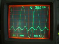
"You waveform is not good....going to triangle.. i hope the frequency is higher related 20 Kilohertz.... my spectation is to have this wave form above 40 kilohertz.... and i will be really happy if this happened into 60 kilohertz."
Carlos,
As you've spotted, that 'scope trace shows the spurious 2MHz oscillation I was getting with 27pF.
As for slew rate limiting at HF, here's the trace at 30kHz, and the distortion residual - no problems there. It doesn't look very different at 50kHz either.
No point in turning it into a DX. I've built that (you've already posted the info I sent you here!), and this is better
Regards,
Brian.
Attachments
Re: I am listening to the Precision model....now great!
Please don't!
destroyer X said:
...
I cannot stop
...
Please don't!
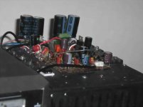
This is not the final schematic...this is what was constructed.
Just to you to see what is going on...nothing is guarantee that will remain, even the input may be modified.
I am extremelly happy with the sonics, already eated the High Resolution II...but there's something that is not exactly perfect.... you will know, in the future, when the solution was found.
I will not ask help because this need people here, at my side..doing with me.... many suggestions will be things i have already tried...so... will not help too much.
The good circuit, aproved and already famous, some CCS, sounds terrible.... so... suggestions may go to those damned ones...the one have to sit with me into my sofa and listen and discuss over the reality he is listening.
Also i want to do by myself...as a challenge.... i wanna prove to myself that i can do something even better (I have doubts... totally better is difficult, maybe partially better)
Now i am more calm...here is the schematic idea...not for suggestions folks..this is to the one are curious only.
I will decide what circuit to install, supress, or adjust...during audition...listening.
regards,
Carlos
Attachments
Thank you Graham, Ecat, Pingrs and Dudainc
But i will answer the one post question..was Andrew T
I have tried variations into resistance value, also i will try into the Precision prototype that is using the same VAS.
The problem, Andrew, is not the point of operation..how advanced the small BC547 is biased... the problem i found is the existance of this transistor draining energy from he VAS input..the whole idea i found terrible,... and when biased (adjusted that resistor into the master emitter...the 22 to 47ohms)... when having signal to drain to negative from the first VAS transistor..it kills the sound quality...turns everything limited...because it is a limiter.... above some level it will drain signal from the VAS input transistor..this is the problem..not the way it is adjusted.
If i adjust, in such a way (the divider) the small BC547 stand without bias to conduct, it will be there doing almost nothing within the audio level range...will be there only disturbing the first VAS transistor.... we can listen differences only because the BC547 capacitance when we install it into the circuit...even with the base disconnected..the capacitance is doing something.
With the transistor biased to 150 milivolts from Base to emitter...Dc stand by bias..... so...not conducting into stand by mode...without audio nothing happens, of course,...but when the audio arrives the transistor goes to work when the amplifier is into the threshold of clipping (because adjusted this way)... this is nice...very good..this is the idea..to protect the VAS transistor..to protect the output drivers, to protect the output...but those ones do not need protection, they are a over kill related power and voltage...so...protecting nothing.... doing nothing positive to the circuit.
Not really doing nothing, it is supressing all transientes, all spikes, all peaks..i do not want that...i do not want limiting inside the audio chain because not good for sound reproduction....with the BC547, the protector, the limiter, the small transistor that drains from the first VAS base...when the one is biased to 150 milivolts in stand by mode...and... at same time i use my supply switch (to generate spikes, to generate bursts, transient signals, pulses), powering on and off, i usually have spikes generated by the switch, because the switch do not have a capacitor.... i can listen the spikes without the BC547...and the spikes goes attenuated when the BC547 is into the circuit..so...it is against what i want.... i do not want to suppress any pulse.... i want all the music envelope reproduced.
I am using a lot of auxiliary circuits, CCS and regulators, but no one of them inside the audio patch.... i have differential, Vas and output (darlington arrangement)...just that, and nothing to disturb into this audio patch..nothing in the middle...all other stuff are auxiliary components, surrounding the main active circuits... they are voltage controls, current stabilizers and so on.
The option to adjust it, that resistance, into master VAS emitter, splitting it, to keep the resistance operating there, into the Master VAS emitter will be already a current limiter to the this transistor (the Master, the one really drives) will be doing nothing there, as the circuit operates fine without that 22 ohms resistance... will be do nothing...would be adjusted to enter into operation into a range of power my amplifier will not reach... will work into unreachable current...just to be there, with the colector to emitter capacitance bothering the first VAS?
I decided to remove the one...but even this way i will do the test you asked.. and soon i will return... i think with the conclusion i have already written above...we gonna see into real world what will happens....observe that only soldering the BC547 colector, and the same BC547 emitter already create differences...so..it cannot be there.
I will use a very huge transistor as VAS Master, also i am already using 2SC5200 and complementary (output units) as drivers.
I think will be hard to burn those ones..very hard.
I hope i was clear..despite the bad english, i made efforts to explain myself.
regards,
Carlos
Attachments
Hi Carlos,
I used a BC547 VAS limiter in the past, and did not note degradation, but then not all circuits work the same.
If you are worried about collector capacitance for the limiting transistor then why not use a small BF*** radio frequency type ?
These will have negligible effect until overload turns it on.
Cheers ........ Graham.
You see dear Graham..you have used in the past..and not using anymore
Why?
Because not good enougth to you...ahahahhaha.
If was really good, your GEM would be using it.
I have tried, because Andrew T asked.
The result was the same... the transistor insertion and work is not good for sound reproduction.
The VAS chapter is closed.
I have tested, tried and it is enougth...i will tweak the rest of the amplifier for better and better sonics.
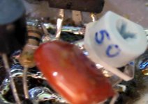
Here is the image, i have tried using 50 ohms trimpot and also i have made an arrangement to 22 ohms variable.
regards,
Carlos
Why?
Because not good enougth to you...ahahahhaha.
If was really good, your GEM would be using it.
I have tried, because Andrew T asked.
The result was the same... the transistor insertion and work is not good for sound reproduction.
The VAS chapter is closed.
I have tested, tried and it is enougth...i will tweak the rest of the amplifier for better and better sonics.
Here is the image, i have tried using 50 ohms trimpot and also i have made an arrangement to 22 ohms variable.
regards,
Carlos
Attachments
This site is about mcintosh power amps specs :
http://mcintoshlaboratory.tripod.com/instruments/poweramps.htm
http://mcintoshlaboratory.tripod.com/instruments/poweramps.htm
I suppose for your ultimate version you would need some sort of protection, I have seen loudspeakers that cost more than my house, I don't think one would like to loose one of those in a catastrophe. I don't even think I'd like to loose a $500 speaker.
You need to make it so much better than the HRII that even with compromises like relays etc., it must still sound better.
If anyone can do it, it is you.
You need to make it so much better than the HRII that even with compromises like relays etc., it must still sound better.
If anyone can do it, it is you.
Hi Carlos,
If an error caused VAS overcurrent in my circuit, the class-A output would empty the 10,000uF and blow the main 6.3A rail fuse before the VAS device or any class-AB devices could blow. Already proven in real life that the circuit has its own peak current limiting capabilities with either input or output overload.
My circuit is different to yours, and that is why I do not use a VAS peak current limiter.
Cheers ............ Graham.
Fuse can protect the expensive speaker
I will think in a good way to avoid problems.
The test i am making are very hard to parts... the amplifier is driving square wave with enormous voltage into the input..i cannot see better way to burn it... and it is working safe.
To burn, only if someone trow bolts and nuts into the board...in your case..under the board...something very stupid this way.
But of course, people can invert things..well...i cannot be responsable of that behavior....also a ligthning can fall..also i cannot include protections.
Someone may use a truck, or a catterpillar over the board...no way...ahahahah..no way!
regards,
Carlos
Dx Precision now is eating HRII into the breakfast.
It will be under testings till December... waiting boards release and people construct the HRII
hehe.... it is sounding special.... i am dancing...very happy...eating all amplifiers i have in my house.
This one is different, an better than the other i have shown a simplified diagram without values.... this one is more simple and better.
I am very near the satisfaction.... research, tweaks are near the end.
To measurements, simulation, it behaves perfect..square wave reproduction fine from 1 hertz to 60 kilohertz (good slew rate)
But it is a bad mood amplifier, you cannot try bad recordings, noisy things, analogic noises into recording...because it show you all defects..even humble from turntables used appear clearly.
Precise...very precise..... Precision is the name
Giaime input will be used...also Cyrus use this diagram too...maybe others, but near us is Giaime.... this input only works fine when transistors are matched...not only NPN but also PNP...all matched, if not matched, result awfull!!!
regards,
Carlos
Attachments
Re: Dx Precision now is eating HRII into the breakfast.
Here's where someone could provide a service to the DIY community and make a little profit. Boards for a project like this are a great help. I think an even greater help would be to provide matched sets of the signal transistors, with the board. It's a real pain to match transistors, and requires that proper jugs are set up for each type and running condition.
If a builder is concerned about cooking the nice matched sets, just put the board together with unmatched transistors and make sure general operation is ok, then plug in the matched pairs.
Sheldon
destroyer X said:. this input only works fine when transistors are matched...not only NPN but also PNP...all matched, if not matched, result awfull!!!
Here's where someone could provide a service to the DIY community and make a little profit. Boards for a project like this are a great help. I think an even greater help would be to provide matched sets of the signal transistors, with the board. It's a real pain to match transistors, and requires that proper jugs are set up for each type and running condition.
If a builder is concerned about cooking the nice matched sets, just put the board together with unmatched transistors and make sure general operation is ok, then plug in the matched pairs.
Sheldon
- Status
- Not open for further replies.
- Home
- Amplifiers
- Solid State
- Destroyer x Amplifier...Dx amp...my amplifier