Bypass Sizing
I try to set it up for 6dB loss at around 2Hz. This is pretty conservative.
If the cathode resistor is say 1K, then 6dB down at 2Hz corresponds to a capacitive reactance of 1K at this frequency; half signal down the resistor, half down the cap.
Formula is Xc = 159000/F x uF, or uF = 159000/Xc x F.
So, for 2Hz and 1000R, this is:
uF = 159000/2 x 1000, or 79.5uF.
NPV would be 100uF in this case.
There are other ways to achieve this figure, but this is a good guide, and very broadband. You should set it up so that the time constant, given by the product of the cathode resistor and the cap size (uF x megohms) gives a reciprocal in Hz which should NOT be matched in any other section of the circuit to avoid resonant phase effects.
Cheers,
Hugh
Hi Andrew,
Re 22uF across the V-be multiplier.
If these multiplier components are all mounted and working in close proximity with the VAS/driers then I am pretty certain that whether any value of C is fitted or not could not be determined by listening tests.
However when the V-be multiplier transistor is remotely sensing temperature away from the pcb, then it would make sense to mount a capacitor on the pcb itself.
Value ? A sub min 22uF is physically small, cheap and convenient, so will do the job just fine.
Maybe a 470nF ceramic would do too, but not as common or cheap.
I have used 10uF either side of the slider on my own circuit. It works fine, though I heard no difference when no capacitor at all was fitted, though the circuit might well not then behave predicatably during overdrive or overload.
(And I quite often drive my amps beyond 'normal' requirements because if they can take overdrive and overload without probs, then they are not likely to be upset during normal operation either.)
Cheers ......... Graham.
Hi ecat,
I would go with your summary.
Amplifiers react at RF frequencies not just AF, and as Carlos has commented - at RF a wire is an inductor.
The V-be multiplier potential is slewing against 0V heatsink ground - a voltage field load on VAS collector.
This is why I prefer to have the VAS device on the heatsink too - minimise voltage field generation on wiring near to the small signal devices.
Hi Nordic,
I now see you just got in just in front of me whilst I was writing this reply.
Cheers .......... Graham.

Re: Bypass Sizing
what, where?
Can someone identify it in schematic attached to post 3077?
Cathode resistor.AKSA said:I try to set it up for 6dB loss at around 2Hz. This is pretty conservative.
If the cathode resistor is say 1K, then 6dB down at 2Hz corresponds to a capacitive reactance of 1K at this frequency; half signal down the resistor, half down the cap.
Formula is Xc = 159000/F x uF, or uF = 159000/Xc x F.
So, for 2Hz and 1000R, this is:
uF = 159000/2 x 1000, or 79.5uF.
NPV would be 100uF in this case.
There are other ways to achieve this figure, but this is a good guide, and very broadband. You should set it up so that the time constant, given by the product of the cathode resistor and the cap size (uF x megohms) gives a reciprocal in Hz which should NOT be matched in any other section of the circuit to avoid resonant phase effects.
Cheers,
Hugh
what, where?
Can someone identify it in schematic attached to post 3077?
Thank you Graham.... about condensers Nordic
They are capacitors too.... as you know have capacitance and normally bigger than the ones we use to call capacitor.
If you understand that a piece of wire is an inductor...and if straigth will be a very small value of inductor and that real capacitors mounted into the circuit, or, copper lines running parallel that will behave alike air core metal capacitors...you will understand that you have capacitance and inductance into every board.
Inductance and capacitance together, will create a "ressonant frequency"... and that frequency will be consequence of how big are a capacitor and how big is the inductor.
If you want some practical example, lets colect a 27 picofarads capacitor, a ceramic one and we can produce a coil, having three turns, and 4 milimeters diameters.... the coil will have the capacitor into its extremes....this will tune, will ressonate, around 100 Megahertz....increasing the condenser..you will tune 80 megahertz or less... increasing the inductor after this capacitor increase, you will have 60 Megahertz.
Of course, decreasing will do the oposite..... decreasing capacitor and decreasing inductor you will have bigger frequencies...till you will have a single coil....or a half coil...and them a piece of wire... with 13 milimeters long.... having capacity around.... into this peace of wire extremes...and it can be a small copper line into the printed board that will colect signal from the feedback transistor to the lifted ground as an example,.... well, this piece of wire, having capacitances around..forming, creating, producing, capacitance together other piece of copper line..and them..ready..you have tuned 300 Megahertz.
If you have a transistor able to oscilate into this frequency, your carrier of radio frequency will start in the moment you bias the transistor connected to this ressonant pair... inductance plus capacitance.
When you increase the capacitor...frequency goes down, and there's a formula for this purpose... using high capacitances, as electrolitic condensers, so big as 22uf, you will tune a very low ressonance frequency....let's imagine 1 cicle each 10 seconds for instance... this will not make the amplifier oscilate...but in certain sittuations you can have this infra, low frequency oscilations too...when audible they call this motor boating.
I hope this clarify a little the board inductances and capacitances, that will bother you if you use high speed transistors... units that can work 100 Megahertz or more will be subjected to those oscilations, will be under the ressonating frequencies you will have into a pc board....
So... distance of trances must be big...say..parallel lines must not go too long creating Long capacitances... distance between lines..big gaps means lower capacitance formed...so...space between lines is important.
Short copper lines means low inductance..low inductances will tune Very High Frequencies.. the VHF spectrum goes to 300 Megahertz and start around 35 Megahertz i think (not precise, just an idea).... so.... your transistors, not working into 200 Megahertz, will probable be free of problems...the ones that cannot go over 10 megahertz will be much more safe...and the opposite is our now a days tradition...to have nice slew rate (and easy of oscilations too... some of them happens driven by the signal that enters the stage... when in stand by mode nothing happens... entering signal.. then the oscilator is triggered to "on" mode.
Audio cables must not run parallel because of that...also one pick the audio from the other and create capacitor plates... two plates of metal form a capacitor, also two pieces of wire, 1 inch long, twisted one over the other will create 5 to 10 picofarads of capacitance...and this, together some inductance (ahahaha...the wire twisted is the inductor)..than oscilations will start... from 200 to 400 megahertz...within this bandwidth for sure.
So.... the selection of high speed units is dangerous and a very good idea is to avoid.
regards,
Carlos
Re: Yes...for sure an evolution Colin...if you wanted me to tell folks you have told me
Hello
I'm learning so much here that I my knowledge did a leap since few month, many things that you can't find in books are in that forum.
For designing myself.. hummm... one day maby.. but I'm a bit maniac, looking ten time everywhere to be sure of what I discover, and that it's in all the things I do in my life, I presume that I'm a bit insecure, but it's also because I love knowledge so much that I have arround 2000 books at home. But books don't say all and asking lot of questions help me to pinpoint on a subject.
But it's long for me to work on small parts, because of blurr vision and concentration difficulty, so I would made one pc board a month, that made sonics testings very long ...I'm a trurtle compare to you... ha ha ha
I presume I use my BD139 for the two transistors of your new VAS ?
Gaetan
destroyer X said:
Gaetan
I like you way to do things.... very humble, even beeing a moving Encyclopedia of Audio.
Thank you by the confidence and the preference.
But i really think, you are able to design and produce things so good as i can...... and also i believe that can do better....and this would be more options to our forum, and your selfdiscovery too.
I feel good watching you just copying...i did it for more than 40 years (45 to be precise)...it is time, also to you, to hold the calculator machine and put your imagination and experience into some practical work.
regards,
Carlos
Hello
I'm learning so much here that I my knowledge did a leap since few month, many things that you can't find in books are in that forum.
For designing myself.. hummm... one day maby.. but I'm a bit maniac, looking ten time everywhere to be sure of what I discover, and that it's in all the things I do in my life, I presume that I'm a bit insecure, but it's also because I love knowledge so much that I have arround 2000 books at home. But books don't say all and asking lot of questions help me to pinpoint on a subject.
But it's long for me to work on small parts, because of blurr vision and concentration difficulty, so I would made one pc board a month, that made sonics testings very long ...I'm a trurtle compare to you... ha ha ha
I presume I use my BD139 for the two transistors of your new VAS ?
Gaetan
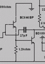
Vas was included, imported directly from Doctor Self Book
The way i found it there...the resistance of 1K2 was increase a little measuring transistor VBE and matching both transistors into VBE.
You can use a small transistor, having higher gain, to the first one and the BD139 is the one i use as the second one.
Better is something you have to judge by yoursef...i have tried 8 types, beeing some of them secrets from Aussie designers (3 different VAS came from them) and i perceived that the free to use ones.... the ones published without copyrigth, Doctor Self and Duncan book this one was the one that have reproduced the most nice sound into my circuit...match my circuit, without problems without harsh or strange sonics.
Also the compression into very low levels was acceptable.
Yes...there are better VAS.... and all them from Aussies, those have copyrigth...people do not want to see those things published.
And because of that...ahahahahha...i think i forgot the schematic.
Dear Gaetan... despite we like one each other very much...we have something that can be compared as "tuned" folks... also we have a problem that forces some distance between us my dear.
You are always trying to discover things, always sniffing and very good to do that, searching into the web and was the only one could find P61 into the web.. also have researched our forum and discovered a lot of Hugh secrets, collecting all his posts and concluding by the ideas he defended, the parts were important and the circuit details are valuable to him.
I have to say you could go very near his designs, so clever you are...but you are into a research to discover those things, when i am into a sittuation not to inform those things.
hehe...a problem between us.... i hope this do not shake our empathy that is great, old and happy.
Some questions you post, are a little bit "poisoned" as to explain details i will give you tracks...and you are not that kind of man that we can repeat tracks hundred times and the one will not understand nothing...you are fast, very inteligent and have a researcher mind....so.... next difficult question... i will give to me, the benefit not to answer my dear friend.
regards,
Carlos
This picture is for Graham ...
Updated my chipamp overnight and this morning... listening to it a bit now... sure improved alot, has more detail than DX, but bass is no where as strong, and treble no where near as smooth, overall character very nice though...
any freed up some large caps for use here... according to your suggestions...
Will you let you know how it went... will be doing this in combination with the 100nf mod.
Attachments
You see Nordic...how good Graham is related circuits
Some good suggestions and than you could improve very fast your amplifier.
he is really great, very famous, have a lot of texts published and defends a lot of interesting theories.
The guy understand form the tubes to transistors, also acoustics and also Radio Frequency.
I suggest you to construct the GEM...will be good to have someone alike you, that use to comment, to show images and to let us follow your steps, publishing things about GEM amplifier.
There is a thread that i have opened..but you can open another one saying, my adventure exploring GEM.
You already made DX.... and sucessfully, maybe another north to follow...i am not selfish, and i think you already contributed a lot.... i think Graham will be happy, naturally, to have you around.
Klaas have started, but professional responsabilities turns hard to him, more obligations, now the boss of a big factory, so...he stopped his GEM work, waiting for better time..when he will return to construct.
You can turn this gap filled by your cooperative work and happy informations, turning the diy happyness functional. also, will make my dear friend Graham laugh loud and happy.
regards,
Carlos
Hi Nordic,
The bass might be lesser in quantity, but firmer in quality when you use large electrolytics on the DX like that.
And of course changing the bass affects the overall balance we hear related to the treble response too.
It will be interesting to hear you findings.
Hi Gaetan,
The common emitter stage in front of the VAS isolates the input/mirror from the VAS base impedance, thus the input/mirror can run at very high impedance and much greater gain.
This gain is turned into lower amplitude distortion via NFB, but phase change within the amplifier has now been much increased beyond that in the original DX, and thus its sound too will be quite different when driving crossover distortion inducing reactive loudspeakers.
Cheers ........ Graham.
Re: Vas was included, imported directly from Doctor Self Book
Hello Carlos
I don't only search on Aksa amp, but also about other amp, preamp, Dac, etc, I have hundreds of files in my computer hard disk and on CD rom, most of the time I ask only to the best guys, it's the only way to learn from the best and I do the same about any subject, in science, technic, spirituality, etc...
Gaetan
destroyer X said:
Dear Gaetan... despite we like one each other very much...we have something that can be compared as "tuned" folks... also we have a problem that forces some distance between us my dear.
You are always trying to discover things, always sniffing and very good to do that, searching into the web and was the only one could find P61 into the web.. also have researched our forum and discovered a lot of Hugh secrets, collecting all his posts and concluding by the ideas he defended, the parts were important and the circuit details are valuable to him.
I have to say you could go very near his designs, so clever you are...but you are into a research to discover those things, when i am into a sittuation not to inform those things.
hehe...a problem between us.... i hope this do not shake our empathy that is great, old and happy.
Some questions you post, are a little bit "poisoned" as to explain details i will give you tracks...and you are not that kind of man that we can repeat tracks hundred times and the one will not understand nothing...you are fast, very inteligent and have a researcher mind....so.... next difficult question... i will give to me, the benefit not to answer my dear friend.
regards,
Carlos
Hello Carlos
I don't only search on Aksa amp, but also about other amp, preamp, Dac, etc, I have hundreds of files in my computer hard disk and on CD rom, most of the time I ask only to the best guys, it's the only way to learn from the best and I do the same about any subject, in science, technic, spirituality, etc...
Gaetan
- Status
- Not open for further replies.
- Home
- Amplifiers
- Solid State
- Destroyer x Amplifier...Dx amp...my amplifier