******* finaly !!!!!!!! been watching multimeter on output now for 2 minutes, pretty soft drift between 3.1 and 3.4mV ...probably due to cheap multimeter.
Gonna take a break now, then wire up an RCA to minijack to test with the mp3 player...
Manny thanks all who helped, especialy Graham... not realy sure what fixed it .... basicaly wrigled all plugs and spades.... figured out that dc trimpot, can only be measured in a specfic polarity... and reset it... removed bias resistors... measured open rails (roughly 35V each)... replaced resistors... and remeasured... and things started looking more like what is expected...
I didn't even realise until I started penciling in the new values on my printed sheet...
"I waana give you my love
A hole lotta love
A hole lotta love"
There she blows people... playing like a nightingale... now only one more channel to get going!!!!!!!!!!
HOOORAAAAYYYY!!!!!!!!!!!!!!
It is on my testspeaker, which is covered in wood dust from the case's construction, and everytime the base drum hits, the dusts flies 2 cm into the air... awesome... I think input is about 500mV at the moment and this thing is seriously damageing my hearing, one ear feels like its ringing allready. Very powerfull. Song went over to one from System of a down now... Wicked.
Heatsink is lieing in worst posible thermal position, and is still staying ice cold with the 50mA bias.
Hi!
Stereo still running good!.... except one channel... I burned it... really sorry... but I already set up a new one...")
Now there is some strange problem.... They can run both only on a single channel (as mono)... on left or on right.... both source channels are normal working.... when connecting as normal stereo on separate
channels one of channels are oscilating at hi frequencies!!!!????
I didn't have this problem with old burned pcb.... can't cantfigure out whats happening because both Dx's on same channel works with no oscilate!?
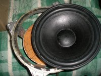
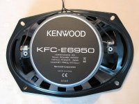
Look at pic and see for yourself what did Dx with my 150Wpeak/50Wrms 8ohm speaker

Stereo still running good!.... except one channel... I burned it... really sorry... but I already set up a new one...
Now there is some strange problem.... They can run both only on a single channel (as mono)... on left or on right.... both source channels are normal working.... when connecting as normal stereo on separate
channels one of channels are oscilating at hi frequencies!!!!????
I didn't have this problem with old burned pcb.... can't cantfigure out whats happening because both Dx's on same channel works with no oscilate!?
Look at pic and see for yourself what did Dx with my 150Wpeak/50Wrms 8ohm speaker
Attachments
Good work Nordic!!!
Soon you will build Dx from nothing to pure strong sound for only two and a half hours ...45 min mill pcb... 1hour assemble parts... 15 min attaching heatsinks... 15min regulations ... 15 min to attach source.. remove protection resistors and connect to speaker.... First Dx I made in two days... second for a half day...
Of course it is only because Dx crew helped... with out them... no sound no nothing...
........................................................
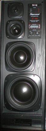
My Dx's are happy now.... new speakers Made in Latvia.. (400Wpeak/100Wrms 8ohms).. "Radiotehnika S-400" Good stuff. Thanks to Dx!!!
.........................................................
Carlos... thanks for great moments looking your great photos. I am extremely busy now... sleeping only 5-6 hours per night... very lot of work...
Soon you will build Dx from nothing to pure strong sound for only two and a half hours ...45 min mill pcb... 1hour assemble parts... 15 min attaching heatsinks... 15min regulations ... 15 min to attach source.. remove protection resistors and connect to speaker.... First Dx I made in two days... second for a half day...
Of course it is only because Dx crew helped... with out them... no sound no nothing...
........................................................
My Dx's are happy now.... new speakers Made in Latvia.. (400Wpeak/100Wrms 8ohms).. "Radiotehnika S-400" Good stuff. Thanks to Dx!!!
.........................................................
Carlos... thanks for great moments looking your great photos. I am extremely busy now... sleeping only 5-6 hours per night... very lot of work...
Attachments
Hi Nordic,
Great to hear of your success - but don't be doing what microp has just done.
Of course I have blown LS too, and regretted it.
When a SS amp is capable of a genuine 100W RMS the LS/driver needs to be specified for the same continuous input.
Cheers ........ Graham.
These are quite tough and good quality too.
Attachments
Dear Microp..please, join all ground to the same point...
a central earth.... central ground....star ground..the name you want...but all grounds goes to the same point.
A metal chassis is better for that purpose.... each transformer, if using two units, will have the central wire, from the secondary, connected to ground...both transformer to ground.
Good luck,
Do not worry, be happy!
Relax, and try to work less, to love more, to dream more....life goes fast... and finishes fast...alike a flash...enjoy your life...with less money and more time to baby.
I have an uncle that was millionaire and died for a heart disease...he worked as an animal for whole life.... near the death he told that his better moments were lived when he was unemployed, starting his life...married, his wife waiting a baby and he was dividing one egg and one potato!.... them he entered into the mania...more....more!...more!..... started to be unhappy...and them he could not more stop...family needs increased.... and all folks surrounding him depending on him...he had to go up...more and more climbing the success and money.
He lived for himself a little...going work, reading, with his driver taking care of transit.... but had not a life.
Heart failed...too much stress.
regards,
Carlos

Re Dx Turbo Version
Hi Carlos
I updated my schematic from the inputs I receive from fellow diy members. I inserted the 180R input resistor. Thank you Graham. P2 was in the wrong position. Thank you AndrewT for that. Is my schematic right now?????? I left C10 and C11 as is. Can I start with the PCB now?
Thanks
macd
Any Comments welcomed. Carlos will this circuit work with the changes I made?
Attachments
Nordic.... of course you can increase, but you will see that above 100 miliamps you
will start to have the low level trebles to be more muted.... the unit will loose some quality.
Go to 80 miliamps or maximum 110 miliamps...then you will feel some heat into your heatsinks...if you want them hot.
regards,
Carlos
.........................................................................................................
Macd
I think it will work fine... i have made fast construction and the result was good.... sonics were not clearly disturbed by this voltage increase.
There are a small error....maybe i made that and have sent the wrong position to the capacitor.
It will be needed between the 4K7 and the Trimpot.... from that point to ground...and do not increase the value...keep 100N, as it can produce influence in sonics.
regards,
Carlos
Attachments
Hi macd,
None of us learn without trying !
However, I still have concerns about your C10/11 arrangement.
You will have more cost and size disadvantage with higher voltage back to back electrolytics than is necessary. Remember; a potential biased electrolytic is going to be running with stabilised operating characteristics and leakage.
There is need to be very careful with this component, thus the advice to parallel it with lesser value components when an electrolytic is used: This because any impedance / leakage induced error developed here is magnified at output by the potential divider ratio of the NFB sense resistors; with the DX this is 17.7 times.
Cheers ......... Graham.
Never mind, be happy.... i hope will not explode
my dear friend Graham.
Was tested real world....assembled...worked.
So, even being correct, of course your ideas are correct...relax man!
This is something customized...people likes to include their own ideas into their future constructions...this makes the circuit belongs to them too.... some artistic or technical touch is welcome..... this condenser, will be more expensive, ugly, bigger, not so stable, but will make that friend happy....let him be happy.
Someone suggested that...and sent me schematic with this "correction"..including those two condensers..other one sent me diodes to protect...this one i did not accepted because generates RFI.... those diodes detect radio frequencies...and clips signals above their own "zener effect " voltages.
If someone send me the schematic and i go making red lines, saying:
- "this is bad, this will not work!...why that foolish here!.... this is stupid!.... do not need that one!"
People will not construct, will feel bad, unsafe, not confortable...and i will lose another nice guy to the crew.
If this will not make the amplifier explode...good politics..let it be there.
The perfectionists are producing ship amplifiers..... enormous as ship...so good as ship related sonics (Navy things produces noises..ahahahah)
I am receiving many mails.... a lot of folks with their own ideas about...people wants, and this is good and natural, to include their own beliefs, their own touch into the "Art"....no problem!...if will not kill entirelly sonics, if will not create hard unstabilities...let it be.
Of course i will not accept responsabilities related non testing things..will not accept complains....i will counter react with three hot ones and 5 boiling ones!
regards,
Carlos
Baah something is funny with the first channel that worked a few weeks ago...
I can set the bias gradualy, down to about 55mA then it drops straight to 25mA.... backing the screw up just increases 25, 26, 27... i.e. normally... but bufore you can get to 55mA, it jumps straight to over 100mA....
Tried setting it to 60mA, which it holds fine as long as powered up... after switching it off.. it starts again being biased at 25mA...
Rail voltages look normal.... even offset is good... scratches head.... guess I'll have to think about it a bit... then try to get the PCB out of the now assembled case....
Attachments
- Status
- Not open for further replies.
- Home
- Amplifiers
- Solid State
- Destroyer x Amplifier...Dx amp...my amplifier