I understand you say this works fine though seems only by the input/output wiring arrangement that it will pickup loads of noise from the traffo. May be that wires are strategically routed to minimize induction..
May you put in simple terms the logic behind a semi fet/bjt output stage?
this is not the first time that BJT and Mosfet was used in an output stage, there are threads here describing such....
better practice
bolts and nuts are not supposed to be relied upon to carry current, as with all other things electrical, this is common practice....
so if the intention was to connect to the metal part, then two ring lugs must contact the metal directly with the bolts and nuts used as fasteners...
bolts and nuts are not supposed to be relied upon to carry current, as with all other things electrical, this is common practice....
so if the intention was to connect to the metal part, then two ring lugs must contact the metal directly with the bolts and nuts used as fasteners...
An externally hosted image should be here but it was not working when we last tested it.

Plug Ugly! relpy
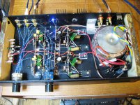
Yep! It does look ratsnesty all right, but that photo was taken about 18 months ago. Matt, the proud owner brought it back in to have the latest circuit mods retro fitted just last week, so I had to "ferret" around in the nest to reconfigure the circuit.
Funny enough though, as Matt likes to run the amp with the lid off and stare in awe at the "mess" inside- oh well, to each their own!
Btw, some folks on this forum are under the impression I am trying to start up as a full-on business. This is not so, as I really do not want to have this as nothing more as a self funding hobby. My lovely wife makes more money as a cleaner than I do building amps! Edward Rotgans of Adelaide Speakers sells on any Quasimodo amp he uses to demo his speakers on if his customers want one, but I don't ever want to be "snowed under" building amps endlessly as I would lose the enjoyment of it as a hobby
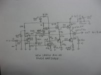
Anyhow, I have included a circuit diagram of a new power amp stage fitted into the existing pcb of an old Sansui AU 101 which I totally recapped and replaced all the transistors. Have a go at tag stripping the circuit as it is very close in its sonic signature to the Quasimodo, but with all bjt's in the output, of course
Yep! It does look ratsnesty all right, but that photo was taken about 18 months ago. Matt, the proud owner brought it back in to have the latest circuit mods retro fitted just last week, so I had to "ferret" around in the nest to reconfigure the circuit.
Funny enough though, as Matt likes to run the amp with the lid off and stare in awe at the "mess" inside- oh well, to each their own!
Btw, some folks on this forum are under the impression I am trying to start up as a full-on business. This is not so, as I really do not want to have this as nothing more as a self funding hobby. My lovely wife makes more money as a cleaner than I do building amps! Edward Rotgans of Adelaide Speakers sells on any Quasimodo amp he uses to demo his speakers on if his customers want one, but I don't ever want to be "snowed under" building amps endlessly as I would lose the enjoyment of it as a hobby
Anyhow, I have included a circuit diagram of a new power amp stage fitted into the existing pcb of an old Sansui AU 101 which I totally recapped and replaced all the transistors. Have a go at tag stripping the circuit as it is very close in its sonic signature to the Quasimodo, but with all bjt's in the output, of course
Attachments


What output capacitor? I cannot see one going to the output post...The output capacitor is too small 0.22R cannot operate there the value is to low ... it doesn't do the job is supposed to be doing
In my opinion, apart from those technical issues pointed out, looks like a well done built one and an original way to go regarding p2p assembly.
With all the respect, I don't think you know how class A really works, check your sources about that.I personally find class "A" amps seem to lack dynamics somewhat- after all, they are running " flat out" with no signal, so where is the headroom for peaks, eh?
There are design philosophies (sounds like an audiophile gimmick) and there are objective facts. Those are the ones pointed out. Going p2p or pcb is a design philosophy. Unshielded untwisted signal wires covering a wide loop, thus having a higher tendency to pick up unwanted signals is not. Try to hear and learn, that's my recommendation.I'm sure many will disagree with my design philosophies, but that's fine with me 'cos it makes for interesting discussions.
Anyway, as I said, construction from both power amp and preamplifier looks quite awesome if we disregard those improper technical implementation issues.
Not done right?!
Good to see your comments Regiregi22, but as I mentioned in a previous post, the Quasimodo suffers no untoward noise pickup that I can detect, nor is it in any way prone to r.f. pickup in the slightest.
My comments on class "A" working come from my personal subjective listening experiences in that I have yet to hear a full class "A" amp to come close to my baby in dynamic scale given a similar rated "on paper" power rating, but maybe there is one out there? I used to own a Sugden A21al once and have built a few of the classic JLH Class "A" variants over the years. I have many tube designs "under my belt" that now gather dust in the spare room, and I have refurbished more tube aspirated amps than I have had hot breakfasts.
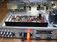
I dunno what Sakis was talking about, as the speaker decoupling capacitors are 2,200 uF 50 volt low esr devices, one on each channel. There is a 0.22 ohm 5 watt wire wound resistor strung between the two 3,300 uF 100 volt main power supply caps. This resistor's small inductance causes a reduction in diode switching noise, and subjectively makes the whole amp sound just a tad more "open" I must give Hugh Dean of Aspen Amplifiers credit for that little trick! Yes folks, The mighty creator of the highly regarded AKSA 55 and the highly reviewed NAKSA 80 modules is a good fiend of mine, and a real amplifier design genius. Check out those NAKSA 80 modules on his site- the nicest looking pieces of pcb art you will ever see- and they sound as good as it gets for a board mounted design!
Good to see your comments Regiregi22, but as I mentioned in a previous post, the Quasimodo suffers no untoward noise pickup that I can detect, nor is it in any way prone to r.f. pickup in the slightest.
My comments on class "A" working come from my personal subjective listening experiences in that I have yet to hear a full class "A" amp to come close to my baby in dynamic scale given a similar rated "on paper" power rating, but maybe there is one out there?
I used to own a Sugden A21al once and have built a few of the classic JLH Class "A" variants over the years. I have many tube designs "under my belt" that now gather dust in the spare room, and I have refurbished more tube aspirated amps than I have had hot breakfasts.I dunno what Sakis was talking about, as the speaker decoupling capacitors are 2,200 uF 50 volt low esr devices, one on each channel. There is a 0.22 ohm 5 watt wire wound resistor strung between the two 3,300 uF 100 volt main power supply caps. This resistor's small inductance causes a reduction in diode switching noise, and subjectively makes the whole amp sound just a tad more "open"
I must give Hugh Dean of Aspen Amplifiers credit for that little trick! Yes folks, The mighty creator of the highly regarded AKSA 55 and the highly reviewed NAKSA 80 modules is a good fiend of mine, and a real amplifier design genius. Check out those NAKSA 80 modules on his site- the nicest looking pieces of pcb art you will ever see- and they sound as good as it gets for a board mounted design!Proper way to earth connecting
Could you please give us a picture or explain how the earth connection should de made?
Thank you!
Could you please give us a picture or explain how the earth connection should de made?
Thank you!
bolts and nuts are not supposed to be relied upon to carry current, as with all other things electrical, this is common practice....
so if the intention was to connect to the metal part, then two ring lugs must contact the metal directly with the bolts and nuts used as fasteners...
An externally hosted image should be here but it was not working when we last tested it.
Could you please give us a picture or explain how the earth connection should de made?
Thank you!
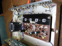
i have said it on my post...just rearrange the two cable ring lugs to be in direct contact with the metal earth plate and use the bolts and nuts to clamp them together, not like that shown in the picture...
if you look at the picture as it is, you have the earthing metal plate, bolt with nut, then one ring lug, nut, then another ring lug, then a nut...
electrically, such practice is not good as you are asking the nuts and bolts to carry current....
this is how i did it on my super leach amp about 20 years ago..

Rod Elliott gives details of an earthing assembly. It does still use a nut and bolt for conduction though, I might be tempted to go toothed washer - washer - approved earth lug to connect more directly.
Earthing (Grounding) Your Hi-Fi
Earthing (Grounding) Your Hi-Fi
Rod Elliott gives details of an earthing assembly. It does still use a nut and bolt for conduction though, I might be tempted to go toothed washer - washer - approved earth lug to connect more directly.
Earthing (Grounding) Your Hi-Fi
I've also read Rod's article -that's why I was asking for further explanation, because there is a conflict between the two ways of earthing.
So, how to do it properly, how's right?
Rod's had one cable yours have two and separated by nuts, what is am pointing out is that those two need to connect together without the nut in between....and much better if those two connects to the earthing plate directly...
in any case yours will work, i am merely pointing out that there is a better way, up to you to use it or not...
in any case yours will work, i am merely pointing out that there is a better way, up to you to use it or not...
IMPO I don't think there's any real difference if there is a nut in between the lugs or not as far as all hardware is new and all nuts are well torqued down.
You can also get copper or brass bolts and nuts if you are overly anal about grounding.
The 2 lugs bolted down without anything in between might actually have a worst contact.
It's far more important that the ground scheme is correct in the first place.
You can also get copper or brass bolts and nuts if you are overly anal about grounding.
The 2 lugs bolted down without anything in between might actually have a worst contact.
It's far more important that the ground scheme is correct in the first place.
You mean the steel nuts and bolts are less conducting?
Alu almost as good as copper as a conductor...
ofcourse. it was the other way around
but on the other side. ring lugs are mostly made out of steel
- Home
- Amplifiers
- Solid State
- Post your Solid State pics here