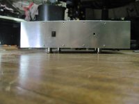
Even more industrial, hydraulic feet (plus Frank the tone-arm Schröder).
=> http://www.holgerbarske.com/etf2010/hb/slides/DSC_0569.html
(sorry, couldn't resist)
=> http://www.holgerbarske.com/etf2010/hb/slides/DSC_0569.html
(sorry, couldn't resist)
While this is a picture thread.... I'm sure some comments will result from what people see. That is how we all learn. As a matter good and safe design, rubber grommets should be used on all holes where wire passes through. Of course, it's always the DIY'er choice whether he/she uses them. But that not withstanding, proper design should be pointed out as AndrewT did. Personally, I don't like learning things the wrong way.Come on guys can we lay off the whole beveled/grommet thing. Keep it to yourself or put it in another thread. This is the last place a discussion like this belongs.
Pics thread = thread for pictures. Not hole finishing techniques.
-N

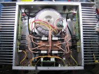
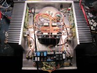
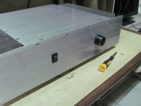
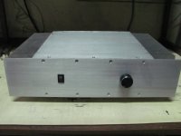
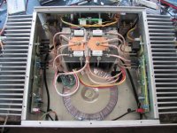
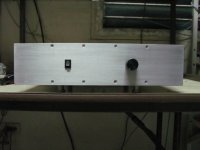
Here's what I've been working on. A P101 high power version stereo amp.
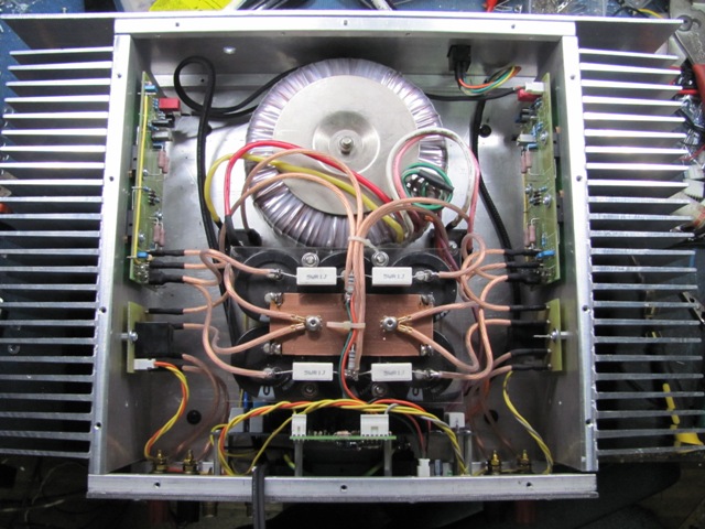
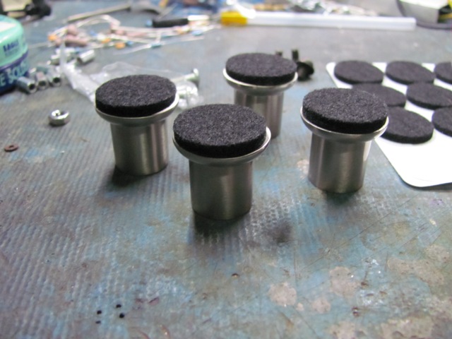
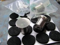
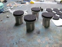
Looking for suitable amp feet, I stumbled in the cabinet supplies in the hardware store. Add some felt discs and viola!


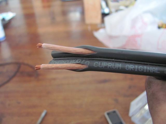
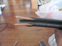
Used Russian Tchernov Audio cables for the internal wiring. Stripped the outer jacket off since it is too thick

Looking for suitable amp feet, I stumbled in the cabinet supplies in the hardware store. Add some felt discs and viola!
Used Russian Tchernov Audio cables for the internal wiring. Stripped the outer jacket off since it is too thick
Attachments
APEX HV23 done by 44250 in action.
APEX HV23 uradio/done by 44250 III. - YouTube
APEX HV23 uradio/done by 44250 III. - YouTube
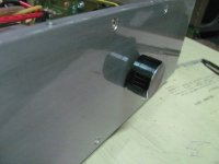
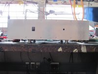
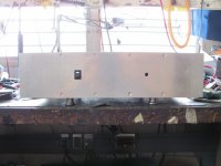
Finished the amp today. Wet sanded the panels with coarse grit paper and then used rub on lettering for the connectors and then applied clear coat. Looked nice to me.
Attachments
Thanks redjr.
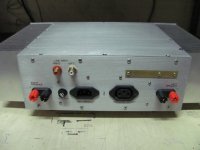
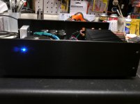
I attached the last pic I took with everything completed inside. It actually sounds pretty good even with jellybean parts used. When the higher quality parts arrive from digikey, I'll take the boards out again and replace them.
I'm actually torn on the power switch LED color. I can't decide to retain the red or change it to white. I also attached pics on how they look with red and white.
Attachments
DjQuan, what did you use for clear coat? It looks great
we posted on the same time lol
I used ordinary clear coat from spray can. I think it was acrylic
edit:
Red for on seems wrong.
Red for danger, maybe.
Red for something gone wrong seems unambiguous.
Grn for OK, or ON seems far better.
Well, the red looks ok to me on contrast with the brushed aluminum and black switch. I no longer like blue because everything seems to use blue led nowadays.
I haven't tried green though. If I'd go green, I'd use the true green ones not the yellow green. I'll give them a try next weekend.
Last edited:
That's a sweet looking layout. Either LED color looks fine. I guess it's just a personal thing.Thanks redjr.
I attached the last pic I took with everything completed inside. It actually sounds pretty good even with jellybean parts used. When the higher quality parts arrive from digikey, I'll take the boards out again and replace them.
I'm actually torn on the power switch LED color. I can't decide to retain the red or change it to white. I also attached pics on how they look with red and white.
You could always go blue as I did (below). It looks much brighter and has that star-burst appearance because of my camera. I went with blue simply because I had built a couple other pieces that used blue so I continued to follow that theme. I could lower the brightness by adding a resistor thus lowering the voltage, but right now it doesn't bug me. Attachments
That chassis looks nice, got more pics of your amp? What design did you build?
If it was 5 years ago, I wouldn't think twice and grab a blue and drop it in. I guess I got over the blue craze now lol
BTW, If you'd like to see more pics/description of my amp, you can see the build log page I made here: P101 Amplifier
If it was 5 years ago, I wouldn't think twice and grab a blue and drop it in. I guess I got over the blue craze now lol
BTW, If you'd like to see more pics/description of my amp, you can see the build log page I made here: P101 Amplifier
Red for ON seems wrong. ... Grn for OK, or ON seems far better.
And green LEDs are so cheap and plentiful ... Blue or near white are more, but not that much anymore.
I always liked an LED - VU meter as a pilot light ... But anyone know where to get these ... Or is DIY better
I just finished up mine about a week ago, and ended up redoing my input cabling due to a ground loop. My build is chronicled here. You can also find more detailed pictures on Photobucket here.That chassis looks nice, got more pics of your amp? What design did you build?
If it was 5 years ago, I wouldn't think twice and grab a blue and drop it in. I guess I got over the blue craze now lol
BTW, If you'd like to see more pics/description of my amp, you can see the build log page I made here: P101 Amplifier
I cheated a little bit and decided to go with some pre-built modules I found on eBay. I used a module built around the LM4702 and decided to just go with the stock parts for my first attempt. Nothing exoctic here.
I worked with a vendor in China, who was very helpful as I needed to communicate with him via email - despite the broken English. I know it's an aging chipamp now, but I'm very happy how it turned out. Maybe I'll be a little more daring on my next build and attempt it from scratch! The build quality of both the amp and PSU are very high IMO. Mine's rated at about 100wpc for the voltages I'm using and really does sound sweet. It's not in full service yet, and has yet to be hooked up to my main, vintage listening rig. I was away at a graduation this past weekend. Maybe this week. It's time!I'll take a look at your link too. Always fun to see how someone else approached their build.
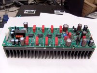
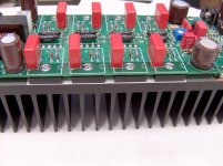
Here's mine. Version 2 of my Class AB ThermalTrak power amp module. Version 1 was posted sometime in 2005 (too many projects, haha).
PCB is 250mm X 75 mm.
Nothing exotic but decent parts used throughout....
4 output pairs for up to 200W/8R output (100W as shown)
100V 105C high temp low esr electrolytics
Silver mica caps for the high freq caps
Wima film caps for decoupling
Mills MRA05 low inductance emitter resistors
Onboard output delay, dc sensing and thermal shutdown
Keratherm White 86 thermal tape
Power and Output connectors are locking Molex Minifit Jr types. Screw/spade terminals are a big no-no here at work. LED color is not mentioned, heh.
Pictures:
1) Overall picture of board
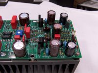
2) Input/VAS detail showing how input TO92 pairs and VAS cascode pairs are thermally connected
3) Output stage showing individual base resistors and Wima 0.68uF MKC decoupling cap
PCB is 250mm X 75 mm.
Nothing exotic but decent parts used throughout....
4 output pairs for up to 200W/8R output (100W as shown)
100V 105C high temp low esr electrolytics
Silver mica caps for the high freq caps
Wima film caps for decoupling
Mills MRA05 low inductance emitter resistors
Onboard output delay, dc sensing and thermal shutdown
Keratherm White 86 thermal tape
Power and Output connectors are locking Molex Minifit Jr types. Screw/spade terminals are a big no-no here at work. LED color is not mentioned, heh.
Pictures:
1) Overall picture of board
2) Input/VAS detail showing how input TO92 pairs and VAS cascode pairs are thermally connected
3) Output stage showing individual base resistors and Wima 0.68uF MKC decoupling cap
Attachments
Last edited:

- Home
- Amplifiers
- Solid State
- Post your Solid State pics here