Does it matter if the shipping costs $25 ???
Chineese post shipping cost is about 10USD, if 30 days delivery is OK for You...
Sajti
Looks great. Why is the pcb perforated?
Somewhere in this fastest growing thread you'll find the answer!
Aksa Lender P-mos Hybrid Aleph (ALPHA) Amplifier
Once more very nice work, everyone loves his own children. I am looking on your scheme and ask you, why only N-channels MosFet are shunted to output, there are equal problems with sharing the current with P-channels. Why you put relatively double value gate stopper, normally are 100E seen for IRFP. I prefer non-polarized capacitor in signal way or to the back loop especially, or combination with fast styroflexes in parallel for best results. How you manage with thermal stability, I many years need to found solution, no any VBE won’t work properly, after puting the some MosFet in VBE, result is excellent stability. BS170 with low threshold is quite complicated to fix on heat sink, IRF have much higher, unapropriate GS threshold, but IRL7833 done this properly.
Thanks, I couldn't see it from the pics.Hi Bogdan,
The PCB isn't perforated. The top side ground plane is. You often see this in products dealing with high frequencies (RF).
-Chris
Anatech:
Actually vias are hollow but plated through. Board is see through essentially like window screen.
Joztom:
This is the 52w Alpha variant - it uses the big IXYS 90amp MOSFETs coupled to a CPU cooler with ceramic insulator (1mm thick) and heatsink paste. Temps of MOSFETs at clamp bar on MOSFET body is 37C for 87w dissipation with fan at slowest 10% speed. The bias is set with the marvelous Aleph CCS circuit by Nelson Pass. It is rock stable and tracks bias via a sense resistor. The DC offset is Hugh Dean’s superb self-tracking design and keeps within 2mV from cold to hot. This amp has zero adjustment pots. I have one installed in prototype Beta. But found that it doesn’t need to be touched so will remove all pots on production build. This is a 3amp bias Class A with zero adjustments for bias or offset. First time turn-on is simple non-white knuckle experience. The Alpha BB is truly a hands of brute of an amp. When running with CPU cooler everything in cool and barely warm so you have no sense that it is running huge currents and power.
Not sure what you mean by need for styroflexes? Using Elna Silmic II with 2.2uF Wima (MKS I think) film on the shunt cap and on the Aleph feedback. They sound quite nice - do you think styroflex is better? Those are not thermally stable. Although when fans work, amp is relatively cool.
220R gate stoppers on on MOSFETs because that is what Hugh specified. Probably ok to use 100R or even 82R. This amp is actually very stable. N channel is the Aleph CCS and goes to the output via the Aleph CCS sense resistor. The P-channel is the active output device and is a common Source output topology. That’s he difference with Aleph which also uses N channel in common Drain output.
Last edited:
Looks like it's been hand soldered. The reason it's gold coloured is the board has been supplied with a ENIG (Electro deposited NIckel Gold) finish rather than the more common HASL (Hot Air Solder Levelled) finish.
ENIG costs more than HASL, but is needed if you've got edge connectors or other contacts on the PCB that you don't want to oxidise. We use ENIG at work on microwave boards too, as the trace thickness is much better controlled than for HASL, so the impedance of microstrip traces isn't messed with.
HASL with no solder mask is good for higher current though for a given trace width, as the (thick) solder coating reduces the trace DC resistance. Nothing stopping you from adding solder to selected traces on an ENIG board though if you need to.
In a production wave solder environment the way to keep ENIG traces and vias from being soldered is simply to cover them with Kapton tape.
@xrk971,
Many thanks for explanation. I will carefully observe the scheme once more. I only ask you to think about some SOS plan, if in any case chiller will be out of service. I already have prepared 6 power amplifiers on tube type heat sink and I will install a small automatic thermostat with on/off limiter for small low noise fan. But with servo nulling is not so critical for get some DC on speakers, because in worst case on overheated IRFP’s immediately both fuses will be blown together, in meantime the safe nulling will be maintained over BD drivers with rest of electricity.
Many thanks for explanation. I will carefully observe the scheme once more. I only ask you to think about some SOS plan, if in any case chiller will be out of service. I already have prepared 6 power amplifiers on tube type heat sink and I will install a small automatic thermostat with on/off limiter for small low noise fan. But with servo nulling is not so critical for get some DC on speakers, because in worst case on overheated IRFP’s immediately both fuses will be blown together, in meantime the safe nulling will be maintained over BD drivers with rest of electricity.
Attachments
Hi Joztom,
If you look here on the top view of the Alpha BB amp, you will see a tiny square PCB with a red LED in the middle. That’s a $3 PWM fan controller with variable set limits for fan speed acceleration, NTC temp sensor, alarm buzzer, and digital fault output. All plug and play with standard computer CPU coolers fitted with 4-pin PWM fans. Clamp a hot MOSFET to one of these heat pipe marvels with fan and the MOSFET won’t even know its passing many amps of current over the voltage drop of the rail voltage.
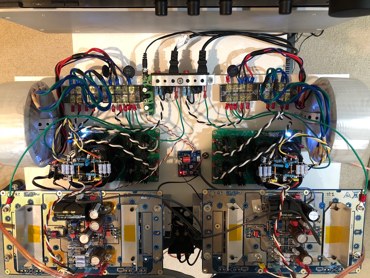
The computer industry has made this space age cooling technology so accessible and affordable that it’s archaic to use natural convection - the least efficient of all means of cooling. Forced air convection can be 100x more efficient and much more compact.
If you look here on the top view of the Alpha BB amp, you will see a tiny square PCB with a red LED in the middle. That’s a $3 PWM fan controller with variable set limits for fan speed acceleration, NTC temp sensor, alarm buzzer, and digital fault output. All plug and play with standard computer CPU coolers fitted with 4-pin PWM fans. Clamp a hot MOSFET to one of these heat pipe marvels with fan and the MOSFET won’t even know its passing many amps of current over the voltage drop of the rail voltage.
The computer industry has made this space age cooling technology so accessible and affordable that it’s archaic to use natural convection - the least efficient of all means of cooling. Forced air convection can be 100x more efficient and much more compact.
The electronics stuffed in the back are convection cooled.Humvees have radiators with fans like any other liquid cooled diesel. What’s your point?
And not knocking what you did, I think it's excellent. Actually very cutting edge for DIY audio. Just mentioning that forced air cooling doesn't work in every instance.
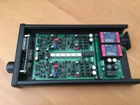
Here's the progress on my new preamp. This'll be sitting on my bedside table, so it's important that it looks reasonably nice.
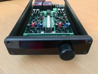
I've used a Hammond 1455 125 x 220 x 30 black anodised case, and machined a front panel from red perspex sheet. This sits over the normal aluminium front panel, hiding the mounting screws for the display board and allowing the nut for the rotary encoder to be recessed.
There's just enough room for my discrete pre board, a little power supply board using a pair of 15W 15V Traco SMPS modules, and the display board.
Once I've got the PIC programmed to drive the volume control stuff there'll be a pair of red seven segment LED displays showing the volume level to the left of the volume adjustment knob I've increased the brightness of the picture showing the front, so the displays can just be made out behind the acrylic front panel. Pressing the knob will toggle power.
Attachments
- Home
- Amplifiers
- Solid State
- Post your Solid State pics here