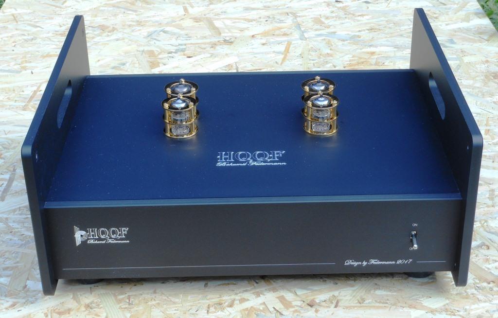
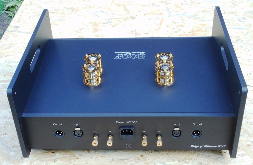
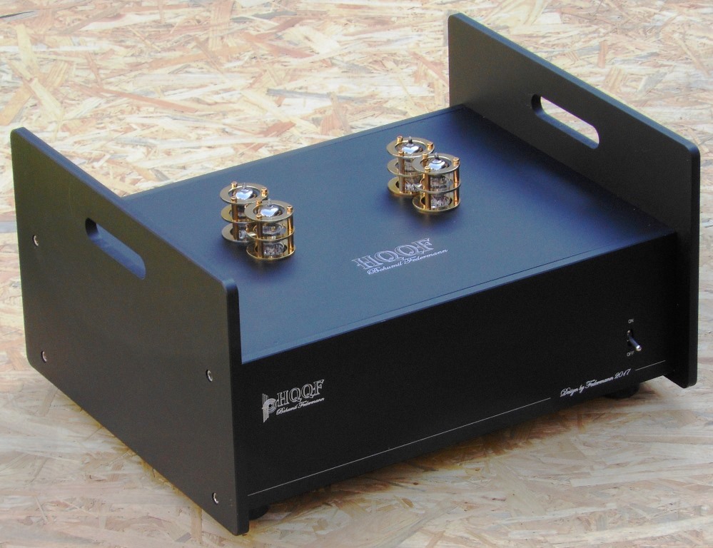
Amp in wooden box, 50s style.
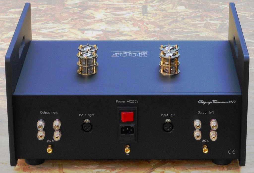
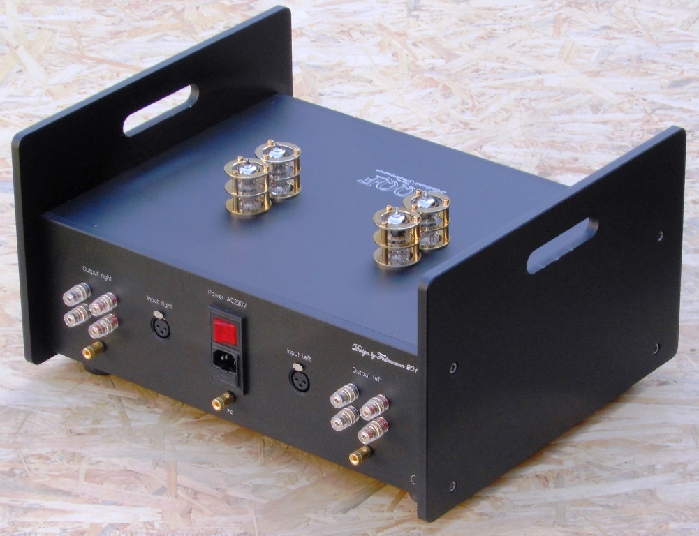
My build of a replica Klipsch wooden Capitol 4 amp/case.
Amp/circuit has nothing to do with Klipsch, but I liked the look of wooden case. I guess not for everybody's taste....
More pictures available on flicker:
https://www.flickr.com/photos/danielminek/albums/72157681532077232/with/34811787122/


My build of a replica Klipsch wooden Capitol 4 amp/case.
Amp/circuit has nothing to do with Klipsch, but I liked the look of wooden case. I guess not for everybody's taste....
More pictures available on flicker:
https://www.flickr.com/photos/danielminek/albums/72157681532077232/with/34811787122/
Just wondering, will you be placing the amp on top of a speaker?My build of a replica Klipsch wooden Capitol 4 amp/case.
Amp/circuit has nothing to do with Klipsch, but I liked the look of wooden case. I guess not for everybody's taste....


That would be nice, but I guess I would need bigger speakers
and two amps...
and two amps...
Just wondering, will you be placing the amp on top of a speaker?
Hi Chris! Glad to see you again, hope you are fine. I'm fairly good and try to follow your advice in our last PM. Some parts are still missing to complete the project, i try to build it with anything had in stock (for that reason the homemade PCB). Regarding the via (or through) holes, are very small pads on both PCB sides drilled with 0.4mm bit (it is the smallest size that can grab the chuck of Dremel). Further, the via (through) connection is obtained with very thin copper wire (d=0.31mm) gathered from 10mm2 multistrand (fine-wire class) electrical cable. It is soldered from both sides on PCB with fine soldering tip and, voila the via connection. Thanks!Hi Fotios!
Long time no hear. How are you these days?
Your boards look extremely good. How do you do your own plated through holes??
-Chris
MX50 SE
Finished one of my four MX50 SE mono-amps! Although in the pics two diodes are missing, but that was corrected
I will be using 2x Avel Lindberg Y236503 160VA 22V+22V Toroidal Transformers and still deciding on my rectifier/psu modules.
I may go with the designs at AudioSector.com, they have an interesting rectifier design. Waiting to hear back if I can order 2x rectifier kits with 2x gold PCB for only the rectifier only, leaving out the amp pcb. Does anyone know if DIYAudio member Peter Daniel runs that site or is connected to it in some way? I figured shooting a PM on here would be faster than emailing the website.
I have 26ga solid core (300V) wire for internal connections and 18ga stranded for audio outputs/inputs.
Does anyone see any possible issues/conflicts with the parts I have given out so far?
DIY Chip Amplifier Kits, PCB's, Components and Information.
Finished one of my four MX50 SE mono-amps! Although in the pics two diodes are missing, but that was corrected
An externally hosted image should be here but it was not working when we last tested it.
An externally hosted image should be here but it was not working when we last tested it.
I will be using 2x Avel Lindberg Y236503 160VA 22V+22V Toroidal Transformers and still deciding on my rectifier/psu modules.
I may go with the designs at AudioSector.com, they have an interesting rectifier design. Waiting to hear back if I can order 2x rectifier kits with 2x gold PCB for only the rectifier only, leaving out the amp pcb. Does anyone know if DIYAudio member Peter Daniel runs that site or is connected to it in some way? I figured shooting a PM on here would be faster than emailing the website.
I have 26ga solid core (300V) wire for internal connections and 18ga stranded for audio outputs/inputs.
Does anyone see any possible issues/conflicts with the parts I have given out so far?
DIY Chip Amplifier Kits, PCB's, Components and Information.
Last edited:
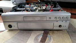
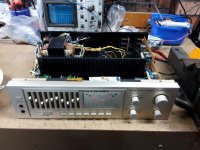
Marantz PM750 resurrection.
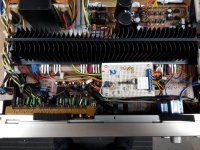
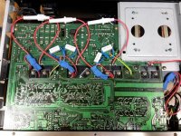
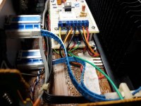
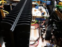
This may be totally left field but I thought I would post this weird setup I have created. I was given A Marantz PM750. Which had faulty power amp section. Both Channel were blown and several attempts were made to repair. the pcb was hacked to the point where desoldering and resoldering before totally damaged the pcb tracks. They were lifting and breaking. It was a mess. Someone attempted to repair it to no avail. So I thought how about retro fitting new amps sections in it and retain all the rest of the preamp and graphic EQ in tact. So I desoldered every component from the power section and removed any live voltages. I didnt want to replace the power supply so I needed a CCT. small enough to sit on top of the cleaned area of the PCB and still run off the +/- 50 volt supply rails. I couldnt think of a simpler CCT. than the nasty John Tirone amp. So I whipped up a pair of these amps on vero board and fitted them in comfortably. The pics will give you an idea what I did. Look before you all go off at me I just wanted the amplifier to work again. To my surprise the amplifer was given a new lease of life! It works remarkably well. It handles the supply rails O.K. It has not blown yet. I matched the differential input to get the offset down to 8mv each. I increase the emitter resistors to 0.68 ohms for extra safety margin. I installed fuses for safety. The preamp gain was raised from a gain of 4 to 6 to match the power stages. I left all the original zobel networks on the output in tact. Even the speaker protector is still operational ( I have tested it). Zero noise and hum. The VU meters were re calibrated and work a treat. As far as the outside is concerned the amp looks original.
Sorry for the long story.
Regards
Billy D...
***********
Attachments
Last edited:
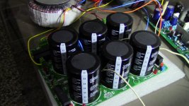
hello guys here is a picture of a prototype power supply that I did together with Mr. ST from Australia the power supply can use a single bridge rectifier or two, capacitance of 45000uF per rail I just thought to placed here all from scratch design 3 months
all from scratch design 3 months Attachments
- Home
- Amplifiers
- Solid State
- Post your Solid State pics here