Bad earthing- again!
Hi AJT and others. I have been guilty in the past of not "doing it right" in the past so far as earthing an amp goes. Check out the rather dodgy "earth lifter" arrangement in an early pre Quasimodo amp I built some time back- for shame!


I have since repented and now do a proper job of it...
But as this post is about showing solid state builds, I thought that I would throw in this rather crazy effort from the past!
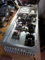
Check it out; no circuit boards, no tag strips, no protection zeners on the output stage mosfets, no output inductor, so source resistor on the p-channel mosfet, no screws holding the output devices to the heat-sink, no protection circuitry and, some would say- no brains involved!
The funny thing is that it sounded very good indeed, and just slightly better than an early version of Hugh Dean's NAKSA 70 that I had just built up.
Hugh is a very generous guy and has only just broken the habit of giving me free samples of his latest pcb creations!
The gent who owns that amp now uses it on his Yamaha NS 1,000's, and apparently it does an excellent job of it! And, after several years of use, it still works a treat- who wooda thunk it!

Hi AJT and others. I have been guilty in the past of not "doing it right" in the past so far as earthing an amp goes. Check out the rather dodgy "earth lifter" arrangement in an early pre Quasimodo amp I built some time back- for shame!
I have since repented and now do a proper job of it...
But as this post is about showing solid state builds, I thought that I would throw in this rather crazy effort from the past!
Check it out; no circuit boards, no tag strips, no protection zeners on the output stage mosfets, no output inductor, so source resistor on the p-channel mosfet, no screws holding the output devices to the heat-sink, no protection circuitry and, some would say- no brains involved!
The funny thing is that it sounded very good indeed, and just slightly better than an early version of Hugh Dean's NAKSA 70 that I had just built up.
Hugh is a very generous guy and has only just broken the habit of giving me free samples of his latest pcb creations!
The gent who owns that amp now uses it on his Yamaha NS 1,000's, and apparently it does an excellent job of it! And, after several years of use, it still works a treat- who wooda thunk it!
Attachments
ne5532 pre-stage
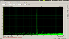
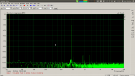
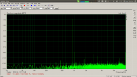
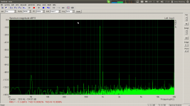
Got my 5532's today and assembled and measured my pre-stage.
First image a reference of the sound-card and the second one channel of the pre-stage. There is some 5 times gain in it.
Got my 5532's today and assembled and measured my pre-stage.
First image a reference of the sound-card and the second one channel of the pre-stage. There is some 5 times gain in it.
Attachments
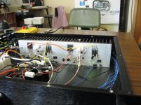
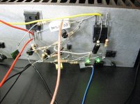
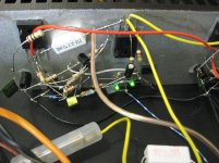
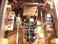
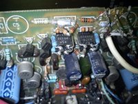
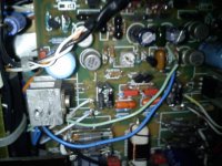
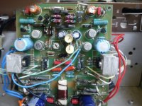
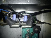
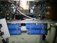
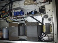
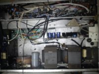
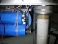
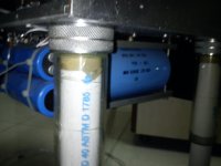
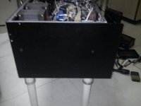
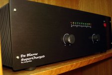
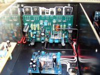
preamplifier transistor amplifier with band limiting
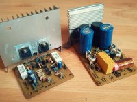
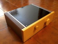
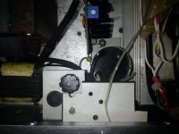
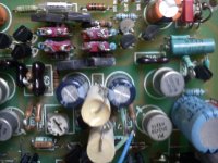
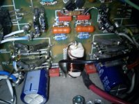
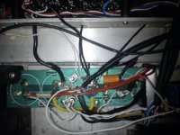
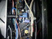
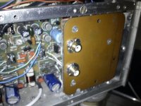
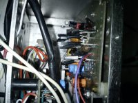
send photos of my amp built for a client gradually send more photos. any comments or concerns I will be responding.
atte. Hernando B.
send photos of my amp built for a client gradually send more photos. any comments or concerns I will be responding.
atte. Hernando B.
Attachments
-
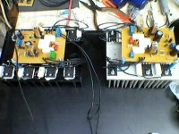 Foto-0189.jpg132.8 KB · Views: 414
 -
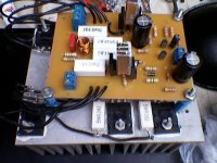 Foto-0191.jpg125.3 KB · Views: 486
 -
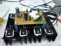 Foto-0187.jpg121.2 KB · Views: 515
 -
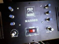 Foto-0181.jpg101.3 KB · Views: 402
 -
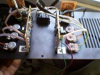 Foto-0178.jpg132.3 KB · Views: 382
 -
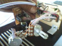 Foto-0172.jpg110.9 KB · Views: 1,558
 -
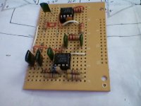 Foto-0165.jpg100.3 KB · Views: 1,625
 -
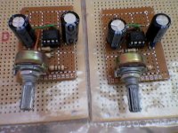 Foto-0164.jpg132.8 KB · Views: 1,700
 -
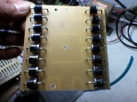 Foto-0158.jpg110.9 KB · Views: 1,749
 -
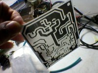 Foto-0152.jpg129.2 KB · Views: 1,806
JLH 2005 based amp
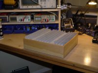
My last amp.
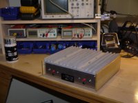
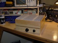
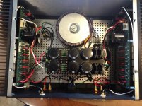
It's a stereo JLH 2005 derated to 5W/ch, about 15+15V dc power supply with capacitance multiplier, 150W transformer, only 1A bias for thermal dissipation reasons (+25°C deltaT on 0.4°C/W heatsinks), paralled TIP3055 output transistors, chassis in black painted chipboard, front panel in spruce.
Almost all materials recycled from the junk bin.
My last amp.
It's a stereo JLH 2005 derated to 5W/ch, about 15+15V dc power supply with capacitance multiplier, 150W transformer, only 1A bias for thermal dissipation reasons (+25°C deltaT on 0.4°C/W heatsinks), paralled TIP3055 output transistors, chassis in black painted chipboard, front panel in spruce.
Almost all materials recycled from the junk bin.
Attachments
My audiophile Leach from mostly recycled parts
It is purely for audio enjoyment and to prove to myself, the readings from DIYAUDIO. Speakers are Klipsch RB81 II
Gajanan Phadte
It is purely for audio enjoyment and to prove to myself, the readings from DIYAUDIO. Speakers are Klipsch RB81 II
Gajanan Phadte
Attachments
It must be Leach amp season. I just completed one on Jens Rasmussen boards in a DIY Audio Store 4U deluxe case.
I wasn't looking forward to tapping the holes, since last time I broke a lot of taps. Funny how much better that went with taps the proper numbered drills from McMaster Carr than the big box store taps and closest regular drill size. The only broken tap resulted from a distraction causing me to lose my grip on the heat sink, and I was able to back the broken part out and finish the same hole.
Unlike Gajanan, I used new parts. Nothing special for resistors, but Wima MKS caps for most of the film caps. The eagle eyed will spot that I goofed when ordering the resistors that set the zener current. Originally thought I'd be using 62V rails, so it was a bit high for the 55V rails I ended up having. A parallel resistor got the zener current back up over 5 mA.
PSU Boards from chipamp.com have 8 of 10 mounting holes that line up with the case's grid, good enough for me. Thank goodness for bringing things up with a variable transformer. I used MUR2020 rectifiers, which have anode and cathode reversed from what is on the silk screen. I hadn't thought that there might be TO220 diodes with the other orientation. Luckily, I noticed the rails were going the wrong way at a couple volts, so saved myself the joy of exploding caps. After reversing the rectifiers everything went smoothly with power up and test.
I have a Leach version 4.2, with resistor referenced cascode instead of the V4.5's and this amp's zener reference. That's just one of the changes that include better film caps and faster transistors, dual PSU, high speed rectifiers, more rail capacitance and of course board layout. I got a decent match of the BC546C/556C input transistors - less than 7 mV offset. All of that makes it hard to decide just what is responsible for the better sound of this new amp, but whatever it is, I like it. There is more low level detail and the sound stage opens up well beyond the speakers with many recordings instead of just a few.
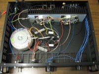
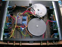
I didn't dress up the store 4U case, so nothing exciting there. Here's a shot of the internal layout. The amps are dead silent. The bridge to the left of the transformer is Pass style ground lift. The two channel grounds join there.
I wasn't looking forward to tapping the holes, since last time I broke a lot of taps. Funny how much better that went with taps the proper numbered drills from McMaster Carr than the big box store taps and closest regular drill size. The only broken tap resulted from a distraction causing me to lose my grip on the heat sink, and I was able to back the broken part out and finish the same hole.
Unlike Gajanan, I used new parts. Nothing special for resistors, but Wima MKS caps for most of the film caps. The eagle eyed will spot that I goofed when ordering the resistors that set the zener current. Originally thought I'd be using 62V rails, so it was a bit high for the 55V rails I ended up having. A parallel resistor got the zener current back up over 5 mA.
PSU Boards from chipamp.com have 8 of 10 mounting holes that line up with the case's grid, good enough for me. Thank goodness for bringing things up with a variable transformer. I used MUR2020 rectifiers, which have anode and cathode reversed from what is on the silk screen. I hadn't thought that there might be TO220 diodes with the other orientation.
Luckily, I noticed the rails were going the wrong way at a couple volts, so saved myself the joy of exploding caps. After reversing the rectifiers everything went smoothly with power up and test. I have a Leach version 4.2, with resistor referenced cascode instead of the V4.5's and this amp's zener reference. That's just one of the changes that include better film caps and faster transistors, dual PSU, high speed rectifiers, more rail capacitance and of course board layout. I got a decent match of the BC546C/556C input transistors - less than 7 mV offset. All of that makes it hard to decide just what is responsible for the better sound of this new amp, but whatever it is, I like it. There is more low level detail and the sound stage opens up well beyond the speakers with many recordings instead of just a few.
I didn't dress up the store 4U case, so nothing exciting there. Here's a shot of the internal layout. The amps are dead silent. The bridge to the left of the transformer is Pass style ground lift. The two channel grounds join there.
Attachments
Last edited:
My last amp.
It's a stereo JLH 2005 derated to 5W/ch, about 15+15V dc power supply with capacitance multiplier, 150W transformer, only 1A bias for thermal dissipation reasons (+25°C deltaT on 0.4°C/W heatsinks), paralled TIP3055 output transistors, chassis in black painted chipboard, front panel in spruce.
Almost all materials recycled from the junk bin.
Just had to say, god damn! What a wonderful looking DIY case!
It must be Leach amp season. I just completed one on Jens Rasmussen boards in a DIY Audio Store 4U deluxe case.
Nice build. Is the PSU of C-R-C construction? I noticed you mounted the TO-264 transistors to the heat sink with spring clips instead of using screws. That too is what I am intend to do with my new build. Would you mind sharing the source of the clips and it spec? Thanks!
- Home
- Amplifiers
- Solid State
- Post your Solid State pics here