Not a scratch build, but a complete nut and bolt tear down and rebuild
Click the link for the full sequence.
An externally hosted image should be here but it was not working when we last tested it.
Click the link for the full sequence.
Not a scratch build, but a complete nut and bolt tear down and rebuild
An externally hosted image should be here but it was not working when we last tested it.
Click the link for the full sequence.
Very impressive work.
Marc
AX6 made in Serbia")
I like the heatsinks! I plan something similar myself some day
very nicely done, good work!Not a scratch build, but a complete nut and bolt tear down and rebuild
An externally hosted image should be here but it was not working when we last tested it.
Click the link for the full sequence.

BK100 test bed
Hi
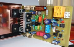
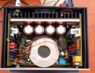
Please find my modded mosfet BK module, I normally put on a chassis 1st to make sure every thing is ok before going into a case. I have used NOS mosfets 2sk174 etc .. relocated the mosfets on a L bracket for easy servicing etc.
best regards
Nick
Hi
Please find my modded mosfet BK module, I normally put on a chassis 1st to make sure every thing is ok before going into a case. I have used NOS mosfets 2sk174 etc .. relocated the mosfets on a L bracket for easy servicing etc.
An externally hosted image should be here but it was not working when we last tested it.
An externally hosted image should be here but it was not working when we last tested it.
An externally hosted image should be here but it was not working when we last tested it.
An externally hosted image should be here but it was not working when we last tested it.
An externally hosted image should be here but it was not working when we last tested it.
An externally hosted image should be here but it was not working when we last tested it.
An externally hosted image should be here but it was not working when we last tested it.
An externally hosted image should be here but it was not working when we last tested it.
An externally hosted image should be here but it was not working when we last tested it.
An externally hosted image should be here but it was not working when we last tested it.
An externally hosted image should be here but it was not working when we last tested it.
An externally hosted image should be here but it was not working when we last tested it.
An externally hosted image should be here but it was not working when we last tested it.
An externally hosted image should be here but it was not working when we last tested it.
best regards
Nick
Last edited:
Hard wired own design
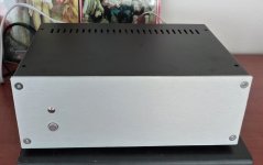
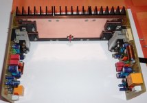
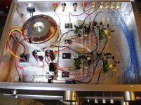
Hi all- my first post and nudie photo of my "Quasimodo" amp design.
This 50 watt continuous per channel into 4 ohms baby drives "Maggie" 1.7's surprisingly well according to Justin the new owner. He much prefers it to his previous Du$$un V8i which really surprised me!
Hi all- my first post and nudie photo of my "Quasimodo" amp design.
This 50 watt continuous per channel into 4 ohms baby drives "Maggie" 1.7's surprisingly well according to Justin the new owner. He much prefers it to his previous Du$$un V8i which really surprised me!
Attachments
post3173
no thumbs up.
look at and fix the loop areas of the various circuits and Inputs/Outputs
eg.
the input wiring from the input sockets travel alone to the selector switch.
The return wire runs off in a completely different direction. That is a loop and the area of that loop determines the sensitivity to reception of interference.
Hi all- my first post and nudie photo of my "Quasimodo" amp design.
This 50 watt continuous per channel into 4 ohms baby drives "Maggie" 1.7's surprisingly well according to Justin the new owner. He much prefers it to his previous Du$$un V8i which really surprised me!
good job...how is the noise performance....aluminum is good at shielding rf....
post3173
no thumbs up.
ok wiseguy, then why not show us how you do it yourself, for once (or first)
@ Richard
Agree with Andrew with this one .... I know it might not sound right but i could call this project a waste of money
Regardless the schematic might be wonderful the implementation is horrible .
There is more : transistors used are of different make and something is telling me that the white labeled ones are really monkeys ( fakes )
Expect crosstalk and channel separation to hit the sky at least
The output capacitor is too small 0.22R cannot operate there the value is to low ... it doesn't do the job is supposed to be doing
still your parts look good but transistor amplifiers cannot be made like that
Looks like another tube guy trying to play in solid state areas ...
Sorry for that is just a personal opinion ...
@ Richard
Agree with Andrew with this one .... I know it might not sound right but i could call this project a waste of money
Regardless the schematic might be wonderful the implementation is horrible .
There is more : transistors used are of different make and something is telling me that the white labeled ones are really monkeys ( fakes )
Expect crosstalk and channel separation to hit the sky at least
The output capacitor is too small 0.22R cannot operate there the value is to low ... it doesn't do the job is supposed to be doing
still your parts look good but transistor amplifiers cannot be made like that
Looks like another tube guy trying to play in solid state areas ...
Sorry for that is just a personal opinion ...
that is why i was asking Richard how the noise performance was...can not tell that from looking at pictures...you can only speculate, let us hear from Richard....
i would rather listen to him than some guy with all talk and nothing to show for in terms of finished amps...
this is a diy forum in case you didn't know, not classroom wherein a teacher tells his class what to do...
- Home
- Amplifiers
- Solid State
- Post your Solid State pics here