How many uH is the choke?Well, i have hundreds of pictures
Will post some of them each week.
Here you have some:
Dx Corporation pictures - YouTube
regards,
Carlos
Houston!... we don't have a problem!
Not critical dear friend...it is there just in case someone use long cables in the output..at home, when using small lenght of audio cables, and standard speakers that uses only a capacitor to the tweeter..then the coil is not really needed.... you can use from 1.5uH to 4uH.
In other words... put something there...it is just in case!
Will attach a picture.... thread is for pictures.
regards,
Carlos
Attachments
Last edited:
First Amp F5 Completed
First of all, I want to thank everybody at the diyaudio forums. I have been a diligent reader that last several months and all the great users and information here as been a supreme motivator and has helped foster a growing passion for electronics and more specifically audio.
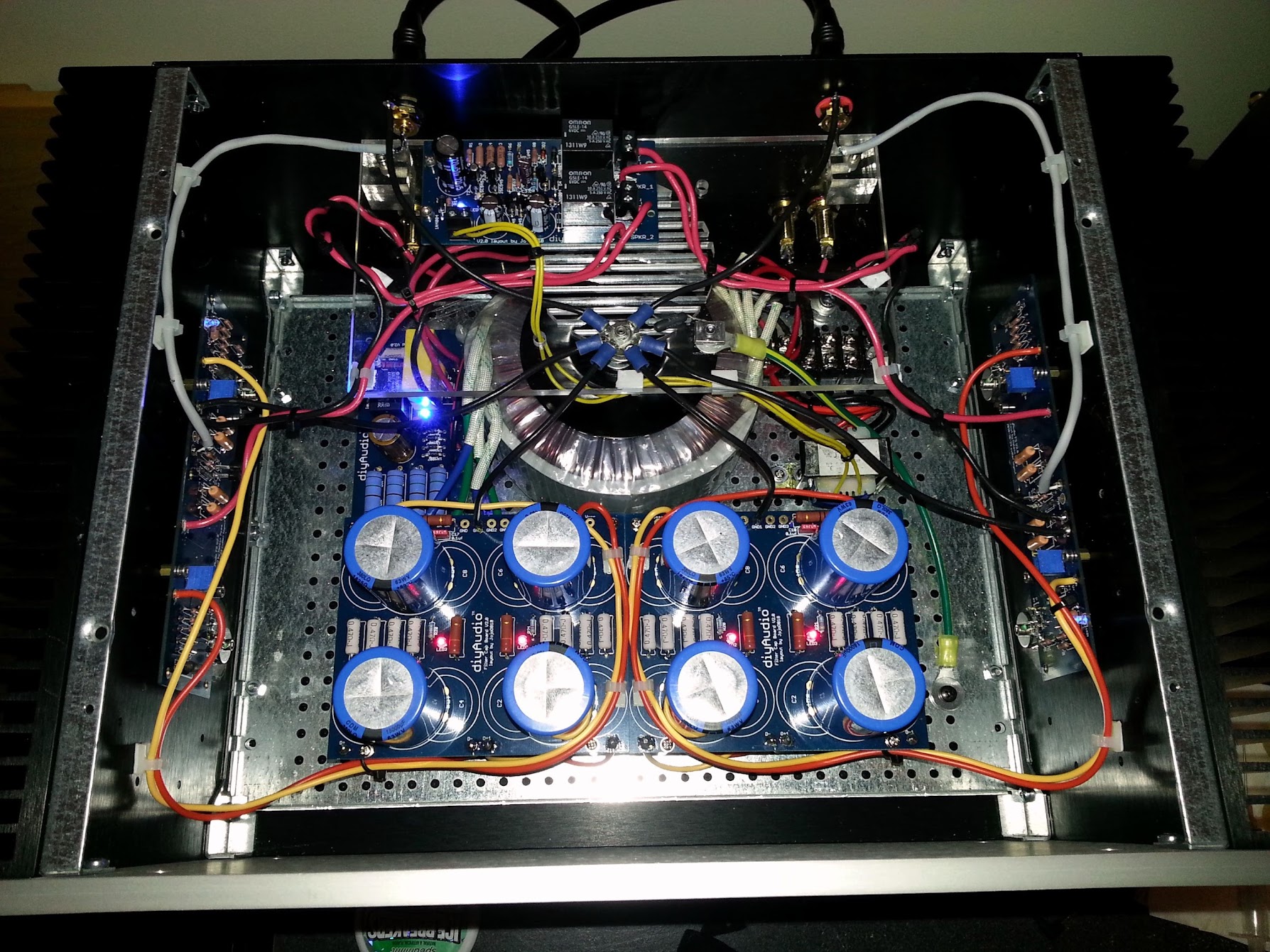
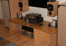
While I am sure I made many rookie mistakes I am proud to present my first creation. The Nelson Pass/Diyaudio.com F5 Amp.
It sounds fantastic!
First of all, I want to thank everybody at the diyaudio forums. I have been a diligent reader that last several months and all the great users and information here as been a supreme motivator and has helped foster a growing passion for electronics and more specifically audio.
While I am sure I made many rookie mistakes I am proud to present my first creation. The Nelson Pass/Diyaudio.com F5 Amp.
It sounds fantastic!
 Post in English please. (Normally - нормально)
First of all, I want to thank everybody at the diyaudio forums. I have been a diligent reader that last several months and all the great users and information here as been a supreme motivator and has helped foster a growing passion for electronics and more specifically audio.
While I am sure I made many rookie mistakes I am proud to present my first creation. The Nelson Pass/Diyaudio.com F5 Amp.
It sounds fantastic!
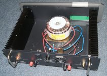
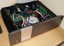
The central ground point should not be the transformer mounting bolt, it should be a separate point isolated from the chassis. The loop breaking resistor should have a pair of high current diodes back to back in parallel with it.
Instead of looping the orange and yellow power supply wiring around the cap boards, take them directly to the channel PCB's.
Thanks for the tips. It only looks like it is on the transformer due to the angle of the picture but its not. It is isolated from everything on a piece of plexiglass and then connected to the chassis via a 10 ohm resistor.
Best regards,
Bill
Oh, and I will make the power supply wiring changes . Though, I need to look into adding the diodes you mentioned to make sure I understand how it will work.
Best regards,
Bill
Oh, and I will make the power supply wiring changes . Though, I need to look into adding the diodes you mentioned to make sure I understand how it will work.
While I am sure I made many rookie mistakes I am proud to present my first creation. The Nelson Pass/Diyaudio.com F5 Amp.
It sounds fantastic!
hey, remember to post it here too
") http://www.diyaudio.com/forums/pass-labs/166784-pictures-your-diy-pass-amplifier-50.html
http://www.diyaudio.com/forums/pass-labs/166784-pictures-your-diy-pass-amplifier-50.htmlThanks for the tips. It only looks like it is on the transformer due to the angle of the picture but its not. It is isolated from everything on a piece of plexiglass and then connected to the chassis via a 10 ohm resistor.
Best regards,
Bill
Oh, and I will make the power supply wiring changes . Though, I need to look into adding the diodes you mentioned to make sure I understand how it will work.
The ground loop breaker is shown in Rod Elliot's power supply schematic HERE
It can also be done with a high current bridge rectifier as shown in figure three HERE.


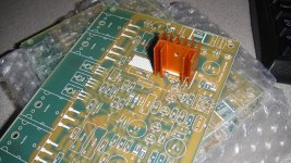
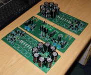
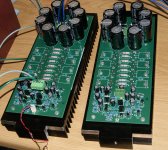
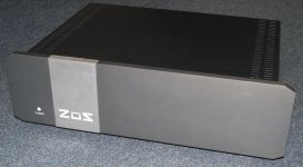
Prototyping of new ZUS power amp is completed and now moving into implementation or pre-production phase.
Attachments

- Home
- Amplifiers
- Solid State
- Post your Solid State pics here