HP,
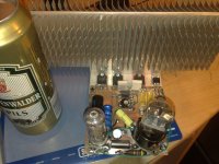
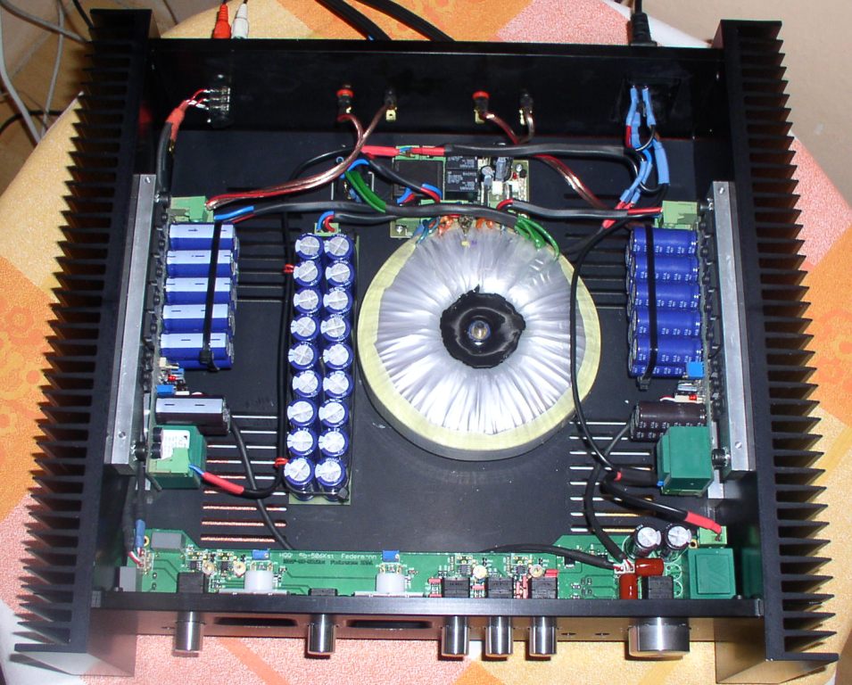
the test assembly shows your PSU connections.
You have at least two tappings from the PSU Zero Volts.
One on the left cap to the left channel and one on the right cap to the right channel. This is wrong.
The three wires from the PSU to each amplifier, zero volts +ve -ve, should be twisted as a triplet and taken to the amplifier as that triplet. At the amplifiers (since it's two channel) the triplet is Y split to form two sets of triplets. One set to each amplifier. Keep these final triplets as short as possible and use low resistance wire in the Zero volts between the two amp boards.
AndrewT--Should the zero volt from power supply go to amp board first and the amp board ground then be connected to chassis (star) ground? Speaker (output) ground go to amp board ground or chassis (star) ground?
I always make errors with it, it is really easy to make a fault, the last time I did burned out the zobel network, the rest stays intact of the hybrid.
You dremel out your own artwork into pcb tracks? That can't be easy!
It's just as bad working on vero-board.
Haha, the prototyping system known as "bread-board" has that name because the original kits for crystal radio sets (and later, valve sets) recomended using Mother's bread chopping board for construction, because it was strong and probably about the right size.
Good luck. I hope you finish it and get it working.
Some of my friends laugh at my Scrap-lifier, but it's a test-bed, not a product being built for use or sale. Proof-of-concept!
Go on kees, keep our dream alive.
not so difficult with a right tool. it is done outside with a protection afcourse.
if it works then I make a board with ultiboard, or better with eagle.
it works faster then with bread board spcial if it is simple.
I am busy (2 year already) with a pcb mill construction, but I am not further then parts, it is expensive.
Last edited:


Hihi I do not such thing, but as economics colaps it is maybe needed.
But if i have everything then I build a pc mill machine, I have no 70 procent of the needed parts, it is expensive so I take time for it.
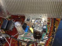
Here the amp is ready for his voltages. 2x 58 volts, 2 x 120 volts, and one 350 volts, so if the dog of my mother comes tomorrow I let him sniff on it.
The bottle of beer is for get some extra balls for the big bang.
But if i have everything then I build a pc mill machine, I have no 70 procent of the needed parts, it is expensive so I take time for it.
Here the amp is ready for his voltages. 2x 58 volts, 2 x 120 volts, and one 350 volts, so if the dog of my mother comes tomorrow I let him sniff on it.
The bottle of beer is for get some extra balls for the big bang.
Attachments
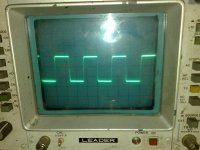
First tests square wave 20 Khz on driver mosfets 2sk1058 and 2sj162 as you see no overshoot, without compensation.
idle current for mustage who drive the power mosfets is 60 mA, and go as high as 100 mA, so I have a lot of drive, witch make speed happy for transients , amp has no feedback and no cathode follower anymore, it was close to simulation, the only thing I did change was the grid resistor for 6C19P 100k was to low, loose of low frequenties.
used tubes 6C19P and 6H8C.
Attachments
Last edited:
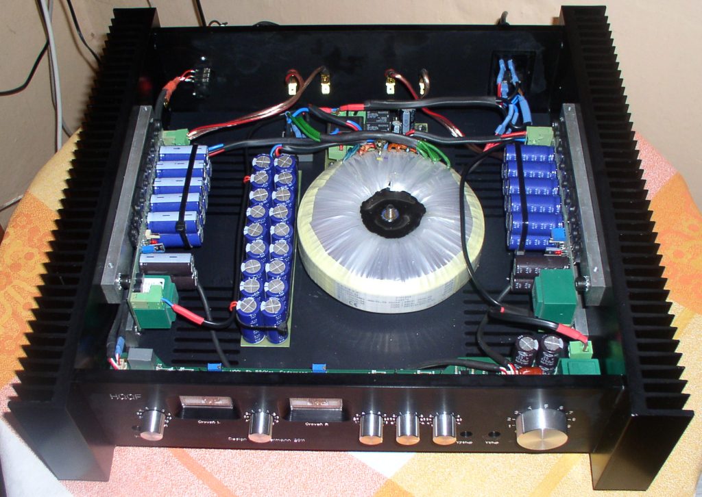
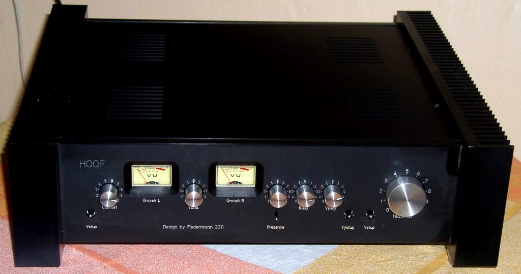
My HQQF pleasure (a few shots and measurements): perys | perys - hqqf_2012 ? rajce.net
it sounds great, very very close to eg. (tube!) Jadis DA-30, and much better than many other amps I could tested and listen during my hifi-voice.com reviews...
it sounds great, very very close to eg. (tube!) Jadis DA-30, and much better than many other amps I could tested and listen during my hifi-voice.com reviews...
Very nice amp Federmann! is that a class A amp? How much capacitance do you have in the power supply?
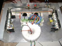
2 x (5+5+9) * 3,3mF
2 x 62,7mF/63V
- Home
- Amplifiers
- Solid State
- Post your Solid State pics here