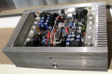
That's a 85' model alpha 230 from Hamamatsu , Japan. 23 years of block parties in the Bronx , new york , another 20 (or 30+ 100v caps everywhere) as "reborn".
I am shaking the house , PS never even gets warm. "Skived" heatsinks really put out the heat. This was good practice for the "DIY" amp's I'm about to make , they will be Soooo easy (compared to this one).
OS
I am shaking the house , PS never even gets warm. "Skived" heatsinks really put out the heat. This was good practice for the "DIY" amp's I'm about to make , they will be Soooo easy (compared to this one).
OS
just-finished μPF Amp
Dear All,
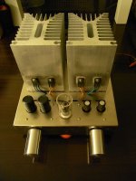
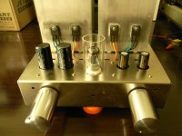
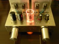
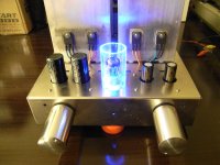
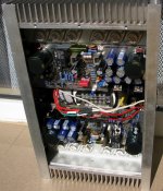
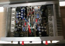
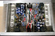
just want to share my excitement with you after finishing my μPF Amp, which stands for μ-follower+power follower.
Since the power follower which is the P version (using 2SJ162 that I had on hand) of Andrea Ciuffoli's amp has "zero" gain, so I decided to add a VAS stage built up with a 5814(ECC82) and a IRF740 in μ-follower configuration to provide a minimum gain and a pretty low output impedance to drive the power follower.
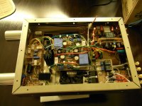
I think there is no need for any comment regarding PF sound performance, most of you are already familiar with SE Amp or PF Amp, here attached with some pictures.
- power off;
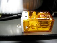
- stand-by mode (glowing red);
- power on (glowing blue);
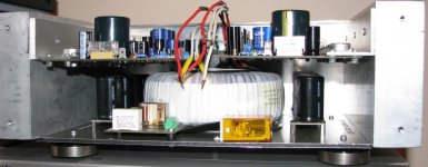
- internal layout.
Dear All,
just want to share my excitement with you after finishing my μPF Amp, which stands for μ-follower+power follower.
Since the power follower which is the P version (using 2SJ162 that I had on hand) of Andrea Ciuffoli's amp has "zero" gain, so I decided to add a VAS stage built up with a 5814(ECC82) and a IRF740 in μ-follower configuration to provide a minimum gain and a pretty low output impedance to drive the power follower.
I think there is no need for any comment regarding PF sound performance, most of you are already familiar with SE Amp or PF Amp, here attached with some pictures.
- power off;
- stand-by mode (glowing red);
- power on (glowing blue);
- internal layout.
Attachments
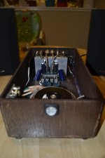
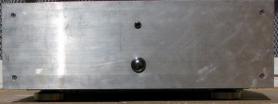
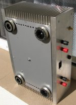
..... my not finished Goldmund amplifier .... weight ,only 11.5 kg .
Alex.
weight ,only 11.5 kg .Alex.
Attachments
Last edited:
..... pictures at request ...
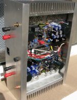
Maybe some guys will advice you to invert downwards the L-shaped alluminum adapter, so to better dissipate heat through the large heatsink.
Is that a dual-winding transformer?
very definitely.Maybe some guys will advice you to invert downwards the L-shaped alluminum adapter, so to better dissipate heat through the large heatsink.
There are two advanatges to inverting the L angle.
1.) the heat transfer interface is moved down towards the optimum height for heat dissipation (~ 40% up from the bottom)
2.) The output devices can be mounted much closer to the heatsink, significantly reducing the thermal resistance of the thin horizontal leg of the L.
There is a small advantage to mounting the To3s on the outside of the L. The inside face will be non-flat and extremely difficult to be corrected to flat. The outside face of the L is also likely to be non-flat but these faces can much more easily be corrected to flat, or at least flat enough.
Last edited:
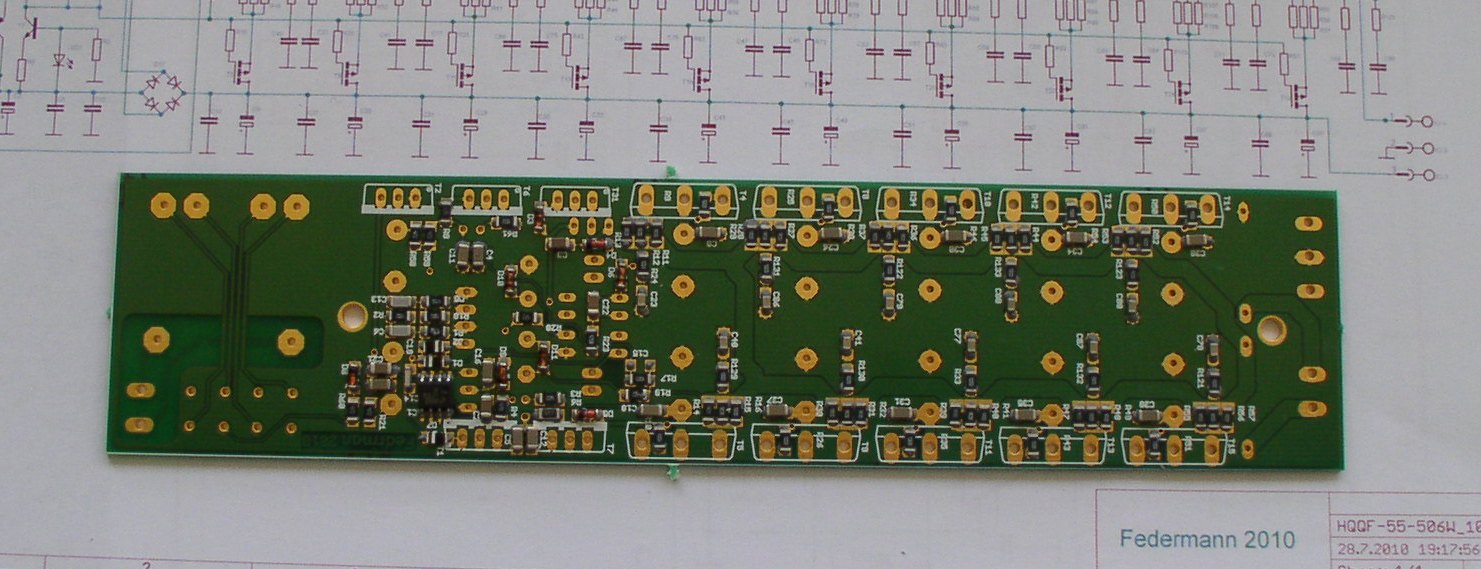
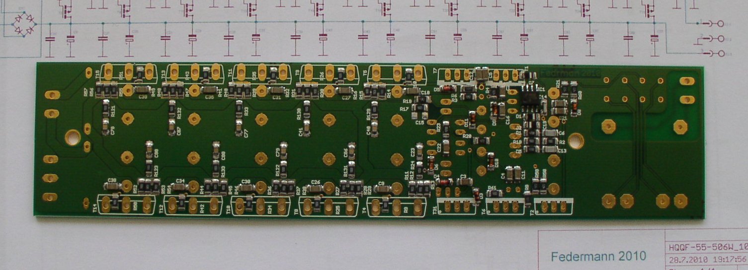
Here's my Borbely 894/211 Clone.
and my Pumpkin / Shuntky
all being built to compliment what will be a DIY-PASS F4
Andy
An externally hosted image should be here but it was not working when we last tested it.
and my Pumpkin / Shuntky
An externally hosted image should be here but it was not working when we last tested it.
all being built to compliment what will be a DIY-PASS F4
An externally hosted image should be here but it was not working when we last tested it.
Andy
Last edited:
Banned
Joined 2002
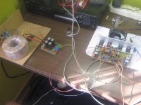
airplane or heli radio box in the background
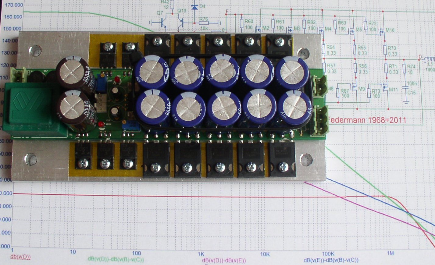
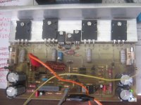
Might as well throw the pictures in here as well.
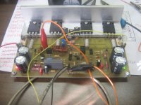
This is my first prototype of a headphone amp, only one channel atm. Still learning the ropes of solid state. Amp does work fine after all the kinks were worked out.
Running only 2n3904/2n3906 and MJE3055/MJE2955. Will try other alternatives in the next version.
-
Kolbjørn
This is my first prototype of a headphone amp, only one channel atm. Still learning the ropes of solid state. Amp does work fine after all the kinks were worked out.
Running only 2n3904/2n3906 and MJE3055/MJE2955. Will try other alternatives in the next version.
An externally hosted image should be here but it was not working when we last tested it.
An externally hosted image should be here but it was not working when we last tested it.
An externally hosted image should be here but it was not working when we last tested it.
-
Kolbjørn
- Home
- Amplifiers
- Solid State
- Post your Solid State pics here