DSO capture of Charisma 0K6 output DC offset
That's enough for today. Tomorrow again
Fotios
An externally hosted image should be here but it was not working when we last tested it.
That's enough for today. Tomorrow again
Fotios
My Whims...
I have a curious sense. It comes probably from my employment with big power loudspeakers and amplifiers for PA use, 27 years ago (from 1983).
The big output power of an amplifier, can covers enough of its - possibly - inherent deficiencies owed to its circuit design or to its implementation with medium quality parts. Of course Charisma 0K6 is implemented with Hi-End quality capacitors and resistors (i don't want to including transistors because there is a big discordance of opinions about them). There is no one part which has inductance (except the enormous output inductor of 0,8μH made from 2mm copper wire) in the signal path.
For the above reason i have an inclination to make amplifiers from 180Wrms/8Ω and above. I place a low limit in my power supplies according to the standard working voltage of capacitors which is 63Vdc. To this, my low limit it is the +/-60Vdc supply rails and the 600VA transformers.
Maybe i am wrong in this curious sense, i don't know.
Fotios
relay selection (driven by a LM3819)
alan
OOPS LM 3914 - run out of edit time
B1, INA-phono-pre, F5
Hi,
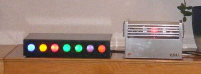
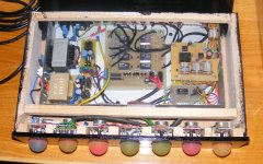
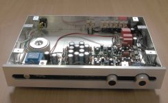
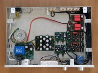
now some pictures of my preamp including a First Watt B1-clone and a INA-phono-pre.
I use it in combination with my F5-clone.
Really nice sound and only some little problems.
In the moment I have some DC/offset in the first seconds (30-60s) and a very little noise with the phono-pre (platINA).
Hi,
now some pictures of my preamp including a First Watt B1-clone and a INA-phono-pre.
I use it in combination with my F5-clone.
Really nice sound and only some little problems.
In the moment I have some DC/offset in the first seconds (30-60s) and a very little noise with the phono-pre (platINA).
Attachments
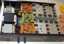
Just finished building and biasing my first power amp, wanted to share
It's Silicon Chip Magazine's 20watt Class A design, no mods. The pre/headphones amp in the second pic are also SC designs, but full of opamps and bipolar electrolytics so next project is a tube/discrete pre, and then tube/discrete h-p amp.
I've had this thing together except for power trafo and output inductor for maybe a year now...
Managed to ninja a pair of 24volt 160VA garden lamp transformers from work, wired 'em up to get 24-0-24 and got the thing going! Will replace with a nice toroid when I can afford it.
Those 'sinks are hot though, i'm worried about the MDF boards. Yes i'm going to have enclosures made ;P
Currently christening it with Devin Townsend's 'Infinity', and then Symbion Project's 'Immortal Game' One loud and full of cymbals, and the other sweet and open, I figure a good way to start my ventures into Class A
It's Silicon Chip Magazine's 20watt Class A design, no mods. The pre/headphones amp in the second pic are also SC designs, but full of opamps and bipolar electrolytics so next project is a tube/discrete pre, and then tube/discrete h-p amp.
I've had this thing together except for power trafo and output inductor for maybe a year now...
Managed to ninja a pair of 24volt 160VA garden lamp transformers from work, wired 'em up to get 24-0-24 and got the thing going! Will replace with a nice toroid when I can afford it.
Those 'sinks are hot though, i'm worried about the MDF boards. Yes i'm going to have enclosures made ;P
Currently christening it with Devin Townsend's 'Infinity', and then Symbion Project's 'Immortal Game'
One loud and full of cymbals, and the other sweet and open, I figure a good way to start my ventures into Class A Attachments
Last edited:
i tdont belive that this will work
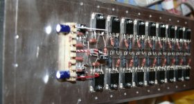
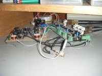
the wire you use to supply all these transitors is way to thin...that apply for both rails and output
meaning that at full power if your rail voltage intransistor 1 is 10 volts in the last tranistor it will be much less ..... much less is even 0.2 volts that also means that in any stress conditions the transistor with less voltage will fail first and take with all the others
you may get away with it if you supply rails and output in the midle of the connstruction but this will onle share the currents meaning that if you have 0.2 volts drop from side to side you will manage to make 0.1 volts from side to side
still this is not enough to make the amp work safe
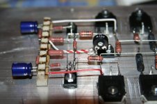
i just noticed that i was in a harry and the rail and output lead is missing also that output resistors are allready curved for something biger .... still the above point is something worth looking at ..... often if length is too much you get problems like that
regards sakis
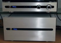
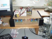
Hi,
I'm working on my new hybrid amplifier. The whole amplifier will be point to point wiring except the protection pcb. The following pictures contains the ss output stage.
Sajti
the wire you use to supply all these transitors is way to thin...that apply for both rails and output
meaning that at full power if your rail voltage intransistor 1 is 10 volts in the last tranistor it will be much less ..... much less is even 0.2 volts that also means that in any stress conditions the transistor with less voltage will fail first and take with all the others
you may get away with it if you supply rails and output in the midle of the connstruction but this will onle share the currents meaning that if you have 0.2 volts drop from side to side you will manage to make 0.1 volts from side to side
still this is not enough to make the amp work safe
i just noticed that i was in a harry and the rail and output lead is missing also that output resistors are allready curved for something biger .... still the above point is something worth looking at ..... often if length is too much you get problems like that
regards sakis
Last edited:
i just noticed that i was in a harry and the rail and output lead is missing also that output resistors are allready curved for something biger .... still the above point is something worth looking at ..... often if length is too much you get problems like that
regards sakis
The rails, and the output will use 2mm thick copper wire. But this wire will be soldered after the mounting of the heatsinks, due I want to curve them using one piece of wire to the capacitors.
Sajti
then yes 2mm thickness of cable is for sure not enough at this length and especially if supplied at the left or right side of your construction
even if terminolgy of electrical laws is used 1.5 mm is good enough for 10A with max 16 and then again 2.5mm is good enough fro 16a and max 20 ....but all the above is for bulding a house and supply lampsand other resistive loads in 50-60 hz freq not amplifiers ....
even if terminolgy of electrical laws is used 1.5 mm is good enough for 10A with max 16 and then again 2.5mm is good enough fro 16a and max 20 ....but all the above is for bulding a house and supply lampsand other resistive loads in 50-60 hz freq not amplifiers ....
Hi Sajti,
I'm inclined to agree, that 2mm is a little on the low side, for the high current links.
If the collectors are middle fed then 2mm would do, but the links to the smoothing caps could/should be dual 2mm.
The emitter cable should be increased to dual 2mm or single 2.5mm and again the output from the middle would be better. Remember that the NFB tapping must come from the output end of the connecting wire.
If your target is 200W into 8ohms (40Vrms) then you must achieve at least 600W into 2r0 (34.7Vrms) to make an effective 4ohm speaker amplifier. Using Cordell's rule for resistive load driving ability then the 2r0 test must be >=1.8times the 4r0 test power. which for 380W (39Vrms) into 4r0 becomes 680W (37Vrms) into 2r0.
then yes 2mm thickness of cable is for sure not enough at this length and especially if supplied at the left or right side of your construction
even if terminolgy of electrical laws is used 1.5 mm is good enough for 10A with max 16 and then again 2.5mm is good enough fro 16a and max 20 ....but all the above is for bulding a house and supply lampsand other resistive loads in 50-60 hz freq not amplifiers ....
The wire will be not too long. The maximum lenght from the capacitors to the last output device will be 25cm. This should be OK.
Each amplifier modul has independent wires.
Sajti
Hi Sajti,
I'm inclined to agree, that 2mm is a little on the low side, for the high current links.
If the collectors are middle fed then 2mm would do, but the links to the smoothing caps could/should be dual 2mm.
The emitter cable should be increased to dual 2mm or single 2.5mm and again the output from the middle would be better. Remember that the NFB tapping must come from the output end of the connecting wire.
If your target is 200W into 8ohms (40Vrms) then you must achieve at least 600W into 2r0 (34.7Vrms) to make an effective 4ohm speaker amplifier. Using Cordell's rule for resistive load driving ability then the 2r0 test must be >=1.8times the 4r0 test power. which for 380W (39Vrms) into 4r0 becomes 680W (37Vrms) into 2r0.
Hi Andrew,
I will try it with 2mm, because I have the wire. If I find any problem, than I will go to double 2mm. I have enough space, and short lenght to change the wire if necessary. I have some 4x2mm flat copper wire as well, so I have chances.
The output will be close to the middle of the emitter wire, to the protection relay, and to the output terminals. The will be no feedback.
The output power is mainly depended by the PSU in my case (16pairs of output devices should be enough for 2ohms load), and the PSU is based on 1500VA toroid, and 198000uF smoothing.
Sajti
and visa versa....ha ha ha ...meaning that often many of so called professional amplifiers last longer (while producing average sound ) but last under a lot of stress cause the power supply is weak ...meaning that when the load is very high rails will dive sound is distorted but amp is safe
in your case a rowbust supply will perform perfectly sound wise but will provide a hell of a lot of current to the boards and that is why you should be twice carefull regarding wiring and power distribution ....
kind regards sakis
in your case a rowbust supply will perform perfectly sound wise but will provide a hell of a lot of current to the boards and that is why you should be twice carefull regarding wiring and power distribution ....
kind regards sakis
and visa versa....ha ha ha ...meaning that often many of so called professional amplifiers last longer (while producing average sound ) but last under a lot of stress cause the power supply is weak ...meaning that when the load is very high rails will dive sound is distorted but amp is safe
in your case a rowbust supply will perform perfectly sound wise but will provide a hell of a lot of current to the boards and that is why you should be twice carefull regarding wiring and power distribution ....
kind regards sakis
The professional amplifiers designed for other purposes. The live music has high peak ratio, so smaller PSU is enough, due the capacitors keep the rails for short time.
Another issues are the price, size, and weight, which are not so important for DIY amplifier.
My amplifier has 1.6m heatsink for one stereo amplifier, which has the weight of 10kg...
Sajti
- Home
- Amplifiers
- Solid State
- Post your Solid State pics here