If the noise is mechanical that could help, but it won't reduce the aerodynamic noise from the fan blades and airstream.
If the fan is new and of good quality the aerodynamic noise should be much stronger than the mechanical noise. Your suggestion makes sense for a used fan though.
If the fan is new and of good quality the aerodynamic noise should be much stronger than the mechanical noise. Your suggestion makes sense for a used fan though.
Hi,
stand that sink on it's end.
Place the fan at the bottom.
Make sure the fan blades are of the correct shape/orientation to blow through the sink.
Ensure minimum resistance to air flow from vents/exhausts.
Use a big slow fan rather than a medium size, medium speed fan.
Don't consider anything under 80mm blade diameter.
120mm will perform better than 100mm.
Duct the air to ensure minimum leakage.
thanks andrew
that is my approach also
regards
AndrewT said:Hi,
stand that sink on it's end.
Place the fan at the bottom.
Make sure the fan blades are of the correct shape/orientation to blow through the sink.
Ensure minimum resistance to air flow from vents/exhausts.
Use a big slow fan rather than a medium size, medium speed fan.
Don't consider anything under 80mm blade diameter.
120mm will perform better than 100mm.
Duct the air to ensure minimum leakage.
that is my approach also
regards
Re: one more
Saki's - Beautiful handcrafted amps , man.") you seem not afraid of a few jumpers to keep your layout symmetrical. We seem to have the same idea on layout with VAS in middle/ output BUS.
you seem not afraid of a few jumpers to keep your layout symmetrical. We seem to have the same idea on layout with VAS in middle/ output BUS.
I have tried every ignorant method short of a hard short to fry this amp. Will bottom out 2 paralleled 15" woofers with the greatest of ease.
I did blow(shot out sparks with inrush) one MOV , but replaced with a larger one on quick connects.
Finally , brought it outside with the 4- 15" fishers to "let er' rip" , it
still had the "symasym" sound standing 300' (80M) away.
I ran some nice emulated minimoog and ARP synthesizers with harmonic laden sawtooth/square content at high volume outside. This actually warmed the heatsinks up for the first time and allowed for me to check Vbias for self -generated thermal response.
Still have 4 unused heatsinks and a nice 300VA "donut" to add a couple of small discrete amps (2 X 50W) for rear channels.
I must give thanks to Mike B.(symasym) , ampslab (Bi120 - sold out?) , and especially Andy C. (LT) for the absolutely AWESOME sound I now hear.
OS
Saki's - Beautiful handcrafted amps , man.
you seem not afraid of a few jumpers to keep your layout symmetrical. We seem to have the same idea on layout with VAS in middle/ output BUS.An externally hosted image should be here but it was not working when we last tested it.
An externally hosted image should be here but it was not working when we last tested it.
I have tried every ignorant method short of a hard short
to fry this amp. Will bottom out 2 paralleled 15" woofers with the greatest of ease.I did blow(shot out sparks with inrush) one MOV , but replaced with a larger one on quick connects.
An externally hosted image should be here but it was not working when we last tested it.
An externally hosted image should be here but it was not working when we last tested it.
Finally , brought it outside with the 4- 15" fishers to "let er' rip" , it
still had the "symasym" sound standing 300' (80M) away.
I ran some nice emulated minimoog and ARP synthesizers with harmonic laden sawtooth/square content at high volume outside. This actually warmed the heatsinks up for the first time and allowed for me to check Vbias for self -generated thermal response.
Still have 4 unused heatsinks and a nice 300VA "donut" to add a couple of small discrete amps (2 X 50W) for rear channels.
I must give thanks to Mike B.(symasym) , ampslab (Bi120 - sold out?) , and especially Andy C. (LT) for the absolutely AWESOME sound I now hear.
OS
Re: Re: one more
thanks OS ...yes !!!! i like my amps to look very symmetric ....often my lay outs have been critisized from forum members for looking symetric but not really follow the ruls for designing amps like feedback traces decoupling caps and so on ...
this paricular lay out is actually not mine forum member intefixes did it and i just made some mods to it to fit it to my standarts ...
my work is actually hidden down under in a couple of small piggy boards and its called
VI LIMITERS !!!!!!!
you see os .... i am in the small PA bussines so my machines have to stand some abuse
in my free time ( not that much lately ) i try to make a board for P3A ( one of my very favourite amps ) that has to be both symmetric but also follow all mentioned rules about amplifier design .... Then it all ends up in hours and hours design that will end up to that ALL THIS CANNOT BE DONE IN A SINGLE LAYER PCB >>>>> and then again i change my mind cause P3A doesnt deserve a dual layer pcb ( too expensive) and then i change my mind and i say I WILL ADD ONLY ONE LINK ONLY ...and then it doesnt work any more ....and then i start again ...it seems harder than any video game ...or so ...been trying for a year now never managed ....ha ha ha
ostripper said:Saki's - Beautiful handcrafted amps , man.
An externally hosted image should be here but it was not working when we last tested it.An externally hosted image should be here but it was not working when we last tested it.
I have tried every ignorant method short of a hard short
I did blow(shot out sparks with inrush) one MOV , but replaced with a larger one on quick connects.
An externally hosted image should be here but it was not working when we last tested it.An externally hosted image should be here but it was not working when we last tested it.
Finally , brought it outside with the 4- 15" fishers to "let er' rip" , it
still had the "symasym" sound standing 300' (80M) away.
I ran some nice emulated minimoog and ARP synthesizers with harmonic laden sawtooth/square content at high volume outside. This actually warmed the heatsinks up for the first time and allowed for me to check Vbias for self -generated thermal response.
Still have 4 unused heatsinks and a nice 300VA "donut" to add a couple of small discrete amps (2 X 50W) for rear channels.
I must give thanks to Mike B.(symasym) , ampslab (Bi120 - sold out?) , and especially Andy C. (LT) for the absolutely AWESOME sound I now hear.
OS
thanks OS ...yes !!!! i like my amps to look very symmetric ....often my lay outs have been critisized from forum members for looking symetric but not really follow the ruls for designing amps like feedback traces decoupling caps and so on ...
this paricular lay out is actually not mine forum member intefixes did it and i just made some mods to it to fit it to my standarts ...
my work is actually hidden down under in a couple of small piggy boards and its called
VI LIMITERS !!!!!!!
you see os .... i am in the small PA bussines so my machines have to stand some abuse
in my free time ( not that much lately ) i try to make a board for P3A ( one of my very favourite amps ) that has to be both symmetric but also follow all mentioned rules about amplifier design .... Then it all ends up in hours and hours design that will end up to that ALL THIS CANNOT BE DONE IN A SINGLE LAYER PCB >>>>> and then again i change my mind cause P3A doesnt deserve a dual layer pcb ( too expensive) and then i change my mind and i say I WILL ADD ONLY ONE LINK ONLY ...and then it doesnt work any more ....and then i start again ...it seems harder than any video game ...or so ...been trying for a year now never managed ....ha ha ha
Re: Re: one more
an MOV wired up correctly will not be affected by any amount of inrush current.
It is there to carry voltage spikes from Live to Neutral.
The inrush current causes the exact opposite effect. A drop in voltage as the source impedance reacts with the very high current peak.
Hi,ostripper said:I did blow(shot out sparks with inrush) one MOV , but replaced with a larger one on quick connects.
an MOV wired up correctly will not be affected by any amount of inrush current.
It is there to carry voltage spikes from Live to Neutral.
The inrush current causes the exact opposite effect. A drop in voltage as the source impedance reacts with the very high current peak.
By andrew T. - an MOV wired up correctly will not be affected by any amount of inrush current.
That's what I was thinking ...why? The fact is that it was the used one from the stealth ..(17 years old)? Do MOV's have a event limit (lifespan)? In tv circuits ,(degaussers) they fail in 10 years,I have seen them crumble to dust.
2nd issue was that the stealth had 2 power supplies , 1 MOV for each 1500VA trafo + 50K uf supply. I am only using 1 trafo with 100kuf (twice the inrush?). The soft start works... after the initial 2 seconds the MOV can be removed with no effect. I am not running the amp through the MOV.
 In the initial 2 seconds the MOV gets very warm but cools down after 5 seconds. The "failure" was not total .. the MOV had a small pinhole that emitted a spark during inrush , the softstart circuit would otherwise complete it duty.
Another issue , on the original ,they fused the neutral ???? The Tom henry electrical manual says no,no, as well as most other sources. I did change this, as I would not want a LIVE amp with a blown fuse.
Line safety on these DIY projects is , in my opinion , more important than the amp itself.

I think there is some confusion about MOV:s and thermistors here. A MOV is an overvoltage protection device. Those things for inrush protection usually used in SMPS are NTC thermistors. The degauss thermistor is a PTC one.
The inrush thermistors usually have some kind of maximum energy rating. It might be specified as the maximum capacitance in an SMPS.
The Crest CA series amps use this kind of thermistor which is then bypassed by a relay after a delay. They are quite big, over 2.5cm (1 inch) in diameter. Maybe you used one that is too small.
I think there is some confusion about MOV:s and thermistors here.
Sorry for the ignorance.. I tend to generalize
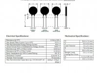
bad habit - like smoking.The faulty Thermistor is a 10A one with a max 90 joules energy rating. http://www.ametherm.com/Data%20Sheets/SL22%202R510.pdf
It (the faulty one) , was taken from a blown 17 YO amp , I replaced it with the 2nd one of the same rating and had no issues yet. To be specific , I did double the rail filter capacitance on on the secondary of the original 1500KVA trafo , would this increase the inrush ? also , do thermistors have a lifespan ?
This device is only 1/2" in diameter.
OS
Attachments
How much capacitance do you have and what is your secondary voltage?
1500VA sec. 53-0-53 w/ 135K uf (amps and main PS) DC = +-77V.
OS
Is 135mF the sum of both rails? That would be equivalent to having 135mF * (53/120)^2 = 26mF after rectifying the mains which seems to be too much for that thermistor (recommended max 6mF). The transformer adds some series impedance though so it might not be as bad as it seems at first.
Yes, I thought it was a little small , MJL21193 (member) has a much larger 1" device for his 1Kva trafo. maybe this would be a good sub :
http://www.mouser.com/Search/Refine.aspx?N=10834088+4294648767+1323043&Keyword=ntc+thermistor&FS=True
16A at 120v - but the equivalant capacitance rating is not much higher than the present one. Maybe 2 of the 8.5A's in parallel ?
mouser does not seem to have the 1" devices.
OS
http://www.mouser.com/Search/Refine.aspx?N=10834088+4294648767+1323043&Keyword=ntc+thermistor&FS=True
16A at 120v - but the equivalant capacitance rating is not much higher than the present one. Maybe 2 of the 8.5A's in parallel ?
mouser does not seem to have the 1" devices.
OS
i realy have to say
that i am really glad to hear from you ...... you ve been away for so long that actually got woried ....
i hope you are realy doing well
now i am more happy ....
best regards my friend ....good to see you
lineup said:so many good pictures sakis
greek audio is the way
Lineup Audio Community recommends Hellas Ella
that i am really glad to hear from you ...... you ve been away for so long that actually got woried ....
i hope you are realy doing well
now i am more happy ....
best regards my friend ....good to see you
these "big" Power Thermistors are expensive.ostripper said:larger 1" device
I prefer cheap Power Resistors, which seem to do the job just as well, when bypassed by a delayed relay contact.
Yeah, that's probably the cheapest option. Those common "sand" rectangular resistors should work. A thermal fuse like those used in home appliances could be put in series for protection if the relay fails to pull in.
If you want to use many small thermistors instead they will need to be put in series, otherwise only one will take the load.
If you want to use many small thermistors instead they will need to be put in series, otherwise only one will take the load.
Re: i realy have to say
I am doing just very fine.
Even if some like hope for me to feel bad.
You are the 'sunshine' of my life. When speaking good words.
Fotios has missed me, too. Very much. We support eachother.
He is one of my best friends .. and so is Gyuri, 'Georg' from Budapest.
Sun
Ella
Fotios - foton, you know what I mean ...
sakis said:
that i am really glad to hear from you ...... you ve been away for so long that actually got woried ....
i hope you are realy doing well
now i am more happy ....
best regards my friend ....good to see you
I am doing just very fine.
Even if some like hope for me to feel bad.
You are the 'sunshine' of my life. When speaking good words.
Fotios has missed me, too. Very much. We support eachother.
He is one of my best friends .. and so is Gyuri, 'Georg' from Budapest.
Sun
Ella
Fotios - foton, you know what I mean ...
AndrewT said:these "big" Power Thermistors are expensive.
I prefer cheap Power Resistors, which seem to do the job just as well, when bypassed by a delayed relay contact.
$3 is expensive? For a 20 amp device that will not burst into flames if the relay doesn't close?
An externally hosted image should be here but it was not working when we last tested it.
$3 is expensive? For a 20 amp device that will not burst into flames if the relay doesn't close?
That's what I want !! The big one..
2R @ 25A = $2.42 usdhttp://search.digikey.com/scripts/DkSearch/dksus.dll?Cat=656273&keywords=sl32
1.18" real big..
THANKS..OS
- Home
- Amplifiers
- Solid State
- Post your Solid State pics here