Pfm
yes, it is... Rather un-usual but compulsory for practical reasons")
Please note this amp is very quiet ( no hum / buzz ) on my 95 DB 1w-1m full range speakers !!
Regards
Rock
Is anything grounded to that painted chassis?
It's pretty, but doesn't appear to follow standard electrical design procedure.
yes, it is... Rather un-usual but compulsory for practical reasons
Please note this amp is very quiet ( no hum / buzz ) on my 95 DB 1w-1m full range speakers !!
Regards
Rock
Attachments
-
 Screenshot_20191223-124534_sahibindencom.jpg709.7 KB · Views: 1,428
 -
 15770946417266772185831085962502.jpg460.8 KB · Views: 552
 -
 Screenshot_20191223-124451_sahibindencom.jpg690.8 KB · Views: 612
 -
 Screenshot_20191223-124458_sahibindencom.jpg941.4 KB · Views: 1,293
 -
 Screenshot_20191223-124514_sahibindencom.jpg734.8 KB · Views: 1,316
 -
 Screenshot_20191223-124511_sahibindencom.jpg449.3 KB · Views: 1,375
 -
 Screenshot_20191223-124524_sahibindencom.jpg253 KB · Views: 1,393
Last edited:
Have used heatsinks ct-540 from cooltec (https://www.cooltec.com/assets/catalog/pdf/ct-540.pdf) for my 4 channel power horse SA2014
For more photos and details have a look here
BR, Toni
Attachments

my amplifier
YouTube
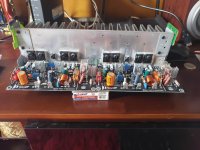
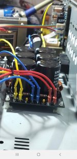
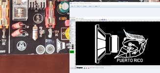
I wonder about those capacitors ...
Axial electrolytics stopped from production some 200 years ago
why use such a part ? so old ?
some stores around the world still sell new parts of axial electrolytics capacitors...
https://www.ecotroncomponentes.com....capacitores+capacitor+eletrolitico+axial&pg=1
https://www.ecotroncomponentes.com....capacitores+capacitor+eletrolitico+axial&pg=1
Axial electrolytics stopped from production some 200 years ago
Really?
Aluminium Electrolytic Capacitors - Axial Leaded | Mouser Greece
some stores around the world still sell new parts of axial electrolytics capacitors...
https://www.ecotroncomponentes.com....capacitores+capacitor+eletrolitico+axial&pg=1
They arent as popular due to amount of pcb space the take up.
A skyscraper takes up less ground space per person than a house does.
Absolutely!!!
I wouldn't think of doing it any other way unless forced by a lack of availability.
Do you remember way back in time when we had to use single ended capacitors on end with a lead folded over to replace those damned radial capacitors? The problem is, there is no easy way to do this the other way around. Not in any way that could be described as "pretty".
-Chris
The next technician. Could be days or years later. Likely for a different fault.But I always figured, who's gonna see them, as long as the job was done properly.
-Chris
AP11 - The Brazilian Mosfet Power Amplifier
Hello guys!
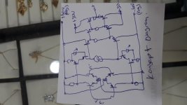
I present here the amplifier of a Brazilian designer called Arnaldo Piacente.
The amplifier uses mosfet outputs and has a DC protection circuit and delay on the board itself.
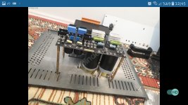
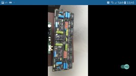
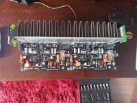
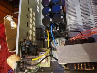
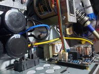
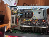
It is an amplifier ( called AP11) based on an APEX model, where the designer made modifications, giving his personal touch. It is specified at 120W @ 8ohms, but in designer tests it easily reaches 140W RMS without distortion or oscillation.
Its THD is very low and the frequency response is flat and goes beyond the usual 20Hz - 20KHz.
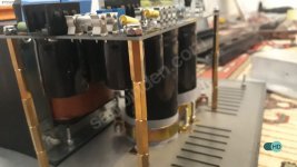
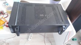
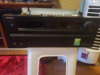
In this assembly, I used as cabinet an Receiver Onkyo TX-NR515 that has the burned HDMI card, which here in Brazil, makes the repair very expensive, not worth doing it.
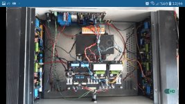
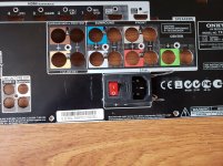
A detail of the assembly is that I had to replace the original Onkyo power transformer because it works at 230VAC and in my city the network is 127VAC. I put in place a 400W power transformer, connected to a 60,000uF capacitance power supply.
I also use a soft start card with a standby power on circuit that was also designed by the same designer as the amplifier.
The preamp board I ordered on Aliexpress is still missing, but I've auditioned by plugging my signal source directly into the amplifier and say the sound is great. It's different from all the amplifiers I have.
It has a warm sound, deep bass that gives the impression of using a subwoofer in the system.
It is not about the excess bass, but the presence of the bass.
Thus, the mid and treble are not suppressed at any time, but also very present and natural.
II really believe this is one of the best, if not the best Brazilian amplifier.
Greetings to all and have a happy new year.
Hello guys!
I present here the amplifier of a Brazilian designer called Arnaldo Piacente.
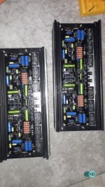
The amplifier uses mosfet outputs and has a DC protection circuit and delay on the board itself.
It is an amplifier ( called AP11) based on an APEX model, where the designer made modifications, giving his personal touch. It is specified at 120W @ 8ohms, but in designer tests it easily reaches 140W RMS without distortion or oscillation.
Its THD is very low and the frequency response is flat and goes beyond the usual 20Hz - 20KHz.
In this assembly, I used as cabinet an Receiver Onkyo TX-NR515 that has the burned HDMI card, which here in Brazil, makes the repair very expensive, not worth doing it.
A detail of the assembly is that I had to replace the original Onkyo power transformer because it works at 230VAC and in my city the network is 127VAC. I put in place a 400W power transformer, connected to a 60,000uF capacitance power supply.
I also use a soft start card with a standby power on circuit that was also designed by the same designer as the amplifier.
The preamp board I ordered on Aliexpress is still missing, but I've auditioned by plugging my signal source directly into the amplifier and say the sound is great. It's different from all the amplifiers I have.
It has a warm sound, deep bass that gives the impression of using a subwoofer in the system.
It is not about the excess bass, but the presence of the bass.
Thus, the mid and treble are not suppressed at any time, but also very present and natural.
II really believe this is one of the best, if not the best Brazilian amplifier.
Greetings to all and have a happy new year.
Attachments
-
 20191222_133415.jpg743.9 KB · Views: 1,473
 -
 20191222_133422.jpg989.5 KB · Views: 1,463
 -
 20191218_182737.jpg721.8 KB · Views: 1,375
 -
 20191226_124857.jpg1,002.3 KB · Views: 1,333
 -
 20191227_200308.jpg796.1 KB · Views: 1,261
 -
 20191227_214607.jpg946.5 KB · Views: 393
 -
 20191228_145223.jpg701.5 KB · Views: 351
 -
 Screenshot_20191228-171627_Facebook.jpg298.9 KB · Views: 313
 -
 20200101_115506.jpg989.8 KB · Views: 380
 -
 20200101_135335.jpg946.2 KB · Views: 533
Last edited:
I suppose that since this thread is about solid state, I can post this little thing here......
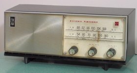
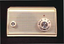
I had an old Panasonic AM-FM table radio laying around, with a damaged case.
I used it out in the garage while I did my woodworking.
So......
I decided to "upgrade" the poor little thing with a homemade case, give it some minor sonic improvements, and maybe find a better use for it.
The Panasonic was a cheap model, solid state, with an AC powered (hot chassis design) chassis.
This means I had to isolate any chances of a shock hazzard.
So...
Fired up the table saw, got some fiberboard and 1/2 inch poplar, aluminum, and other crap, and went to work.
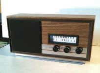
I re-made a custom dial on an aluminum backing, added LED dial illumination, and new knobs, and used a larger speaker, along with chassis changes to improve the sound.
Peaked up/aligned/recapped the chassis too.
Here are pics of what the radio originally looked like, and the woodgrain enclosure that I made - it came out quite nice.
I had an old Panasonic AM-FM table radio laying around, with a damaged case.
I used it out in the garage while I did my woodworking.
So......
I decided to "upgrade" the poor little thing with a homemade case, give it some minor sonic improvements, and maybe find a better use for it.
The Panasonic was a cheap model, solid state, with an AC powered (hot chassis design) chassis.
This means I had to isolate any chances of a shock hazzard.
So...
Fired up the table saw, got some fiberboard and 1/2 inch poplar, aluminum, and other crap, and went to work.
I re-made a custom dial on an aluminum backing, added LED dial illumination, and new knobs, and used a larger speaker, along with chassis changes to improve the sound.
Peaked up/aligned/recapped the chassis too.
Here are pics of what the radio originally looked like, and the woodgrain enclosure that I made - it came out quite nice.
Attachments
Hi wiseoldtech,
Very nicely done! I really like your work.
I enjoy restoring old radios like yours, but older using tubes. So I was happy to see you posted a radio like that.
-Chris
Thanks, Chris.
I'm pretty much a "perfectionist" when I design and build "custom-made" stuff like that radio, which is now part of my "one-of-a-kind" collection.
I adhere to, and am critical to, minute/tiny details that have to satisfy me, which take more time to get right, however, in the end, it just about looks and performs like something "store-bought".
Measurements of such things like the cabinet, screw holes, etc., all get made to within a tiny fraction of a millimeter. - call me obsessed and picky!
And yes, I'm also well-versed on tube stuff as well.
I'm also impressed with some of the stuff others on here have built too, of course.
Through the years, my customers have known my skills, and lord knows that once word spread, I was flooded with work which I thought would never end.
It's nice now, to be semi-retired, taking my time, enjoying life, not having to rush.
I can still remember, back in 1967 at the tender age of 14, building a little tube amp on an aluminum chassis, learning resistor color codes, and tube functions, text books, etc.
That tube amp had a 35Z5 rectifier, a 12SQ7 preamp, and a 50L6 output.
And a tone control.
And it sounded great!
Later on, in High School, in electronics class, I built a Graymark 510 tube radio kit (All American Five), which was popular among students in my class.
Who would have known my interest in electronics would have taken my all the way to retirement age?
Attachments
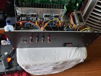
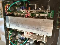
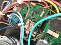
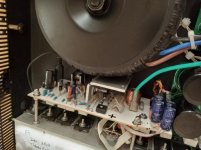
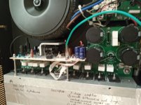
The modified Wharfedale S1500 amplifier.
This modification was the result of amplifier failure, which manifested itself in low amplication on both channels, with one channel much severely affected. For me, it was most unwelcome, as I was very fond of this amplifier. At first, I sought repairs by the seller's technical stuff, but then, realising the cost of this path, I decided to try what I could do. Thanks to this forum, this modification was possible.
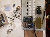
In the attached photos the white PCBs are my creation and work. The green PCBs are from the original circuitry. The amplifier stages prior to the driver stage, excluding the smoothing stage of the power supply, were all sawed off. The white PCBs were all produced at home using rudimentary old methodology to draw the track lines.
This modification was the result of amplifier failure, which manifested itself in low amplication on both channels, with one channel much severely affected. For me, it was most unwelcome, as I was very fond of this amplifier. At first, I sought repairs by the seller's technical stuff, but then, realising the cost of this path, I decided to try what I could do. Thanks to this forum, this modification was possible.
In the attached photos the white PCBs are my creation and work. The green PCBs are from the original circuitry. The amplifier stages prior to the driver stage, excluding the smoothing stage of the power supply, were all sawed off. The white PCBs were all produced at home using rudimentary old methodology to draw the track lines.
Attachments
- Home
- Amplifiers
- Solid State
- Post your Solid State pics here