The audio stuff built by people ( be it speakers and amps) gives one joy and enormous satisfaction and is a very good pastime.
I have come to understand that learning is part of the DIY process. like "necessity is the mother of invention" equals "problems in DIY builds makes one learn the WHY?".
my opinions
I have come to understand that learning is part of the DIY process. like "necessity is the mother of invention" equals "problems in DIY builds makes one learn the WHY?".
my opinions
Learning something Then forgetting
Sometimes these comments can be off putting to participants.
Even so I would like to thank all of the posters who contribute meaningful advice and reminders of correct procedures for best results.
I have just rewired my speakers returns back to the power board after previously redesigning the layout of my LJM L20 to surprising even small results. Simply forgot that one, when in a hurry to get it up and running,Will soon have my eyesight back to near normal and finalize the
amplifier. Still need some advice BUT ???
I am not sure the layout is at its best but it will more than do for now.
Yes it was at least 50 years ago when I first was advised about that essential design requirement.
I wonder how many glorious memnber of this forum will remember everything for that period of time.
Must admit at my age and history in the hifi world I am somewhat bemused and sometimes annoyed at the testosterone filled comments or is it some times alcohol.Indeed, you learn something at least...
Sometimes these comments can be off putting to participants.
Even so I would like to thank all of the posters who contribute meaningful advice and reminders of correct procedures for best results.
I have just rewired my speakers returns back to the power board after previously redesigning the layout of my LJM L20 to surprising even small results.
Simply forgot that one, when in a hurry to get it up and running,Will soon have my eyesight back to near normal and finalize theamplifier. Still need some advice BUT ???
I am not sure the layout is at its best but it will more than do for now.
Yes it was at least 50 years ago when I first was advised about that essential design requirement.
I wonder how many glorious memnber of this forum will remember everything for that period of time.


The audio stuff built by people ( be it speakers and amps) gives one joy and enormous satisfaction and is a very good pastime.
I have come to understand that learning is part of the DIY process. like "necessity is the mother of invention" equals "problems in DIY builds makes one learn the WHY?".
my opinions
Well said Prasi.
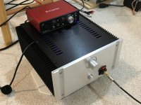
Silicon Harmony - 5w into 8R and 800mW into 50R SE Class A with zero global feedback. Designed in collaboration with AKSA, layout by Prasi. Uses JFET input and BJT/MOSFET CFP output and LED controlled MOSFET CCS. Just a fit check and noise/thermal check with case. So far everything is working out very well. No noise, no hum. Heatsinks at 55C. Sweet SE harmonic profile and wonderful dynamics.
The wiring is still in need of tidying up so don't flame me. This is a fit check.
The wiring is still in need of tidying up so don't flame me. This is a fit check.
Attachments
Last edited:
Interesting. How much voltage gain is produced from the common source input fet? I assume the CFP output is unity gain for better linearity.
How well controlled is the power on impulse at the speaker terminal, after the output coupling cap?
Cheers
Christian
Hi Christian,
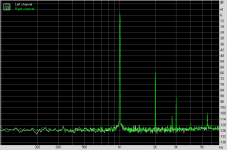
The voltage gain of the BF862 (20v device) is what limits the max power of the unity gain output stage. So max voltage gain is 17.7v p-p. Good question about turn-on/off impulse: there is none - a gentle start up (1 second) and slow decay over about 10 seconds on power off. I have 66mF of RCRCRC supplying power though. So no relay for turn on or off thump protection needed.
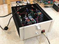
my MX50SE
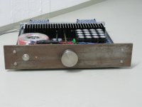
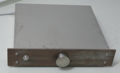
i did this amp a while ago for my friends desktop.
since i wanted something different for the front i decided to take corten-steel
that was bathed in bathroom-cleaner for a few hours
and then dry-cloth-polished: fantastic stains!.
the volume knob is an abused v2a doorknob.
great amp; thanks to LJM!
i did this amp a while ago for my friends desktop.
since i wanted something different for the front i decided to take corten-steel
that was bathed in bathroom-cleaner for a few hours
and then dry-cloth-polished: fantastic stains!.
the volume knob is an abused v2a doorknob.
great amp; thanks to LJM!
Attachments
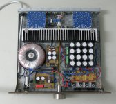
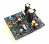
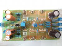
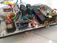
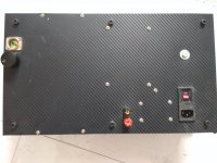
Here is my subwoofer amplifier using Shaan's PEECEEBEE V2 , with 2 pairs of lateral mosfets.
the amp case is made from waste material, a piece of 1 inch thick mdf makes the base, top is a aluminium base plate of my stereo amp chassis, that was lying unused for 3 years. The case earlier housed a p3a and was being used as a sub amp, but wanted something more powerful.
The stainless steel spacers that you see are made from curtain pipe.
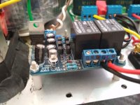
Since amp pcb didn’t have provision of fuse, i mounted the fuses just outside the pcb.
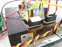
everything including trafo, PSU , heatsink and amp is mounted to the aluminium base plate and is fitted upside down on the MDF base.
Here are some of the pics. The supply is +/-50V. The amp has volume control and protection ckt and is driven by LFE out from a 7.2 ch home theatre receiver. Crossover is by receiver and The subwoofer is an 8” Dayton DVC (4 ohms) housed in a 30 liter vented box tuned to ~ 30Hz.
Sound-wise, it produces enough sound to rattle windows and other things. While testing it on full range 93dB speaker, there is no hiss /hum of any kind, and sound is neutral and not harsh nor subdued.
Since the case is open from all sides, I plan to make an acrylic box with top and bottom open and place it over the amp, for safety.
regards
Prasi
the amp case is made from waste material, a piece of 1 inch thick mdf makes the base, top is a aluminium base plate of my stereo amp chassis, that was lying unused for 3 years. The case earlier housed a p3a and was being used as a sub amp, but wanted something more powerful.
The stainless steel spacers that you see are made from curtain pipe.
Since amp pcb didn’t have provision of fuse, i mounted the fuses just outside the pcb.
everything including trafo, PSU , heatsink and amp is mounted to the aluminium base plate and is fitted upside down on the MDF base.
Here are some of the pics. The supply is +/-50V. The amp has volume control and protection ckt and is driven by LFE out from a 7.2 ch home theatre receiver. Crossover is by receiver and The subwoofer is an 8” Dayton DVC (4 ohms) housed in a 30 liter vented box tuned to ~ 30Hz.
Sound-wise, it produces enough sound to rattle windows and other things. While testing it on full range 93dB speaker, there is no hiss /hum of any kind, and sound is neutral and not harsh nor subdued.
Since the case is open from all sides, I plan to make an acrylic box with top and bottom open and place it over the amp, for safety.
regards
Prasi
Attachments
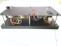
ideally, yes there should have been a hole thro the top and heatsink exposed, but heatsink didnt get even get warm even in present situation. its quite big, 196mmx 150mm x 40mm. its a low dissipation amp, with o/p bias of 30 mA.
earlier a p3a was installed and worked quite fine for 6 months and H/S slightly warm even after playing for hours in indian summer. i guess, the sides being open and top plate is aluminium is helping with dissipation.
earlier a p3a was installed and worked quite fine for 6 months and H/S slightly warm even after playing for hours in indian summer. i guess, the sides being open and top plate is aluminium is helping with dissipation.
Hi venar,
Its the 2 pair version of the amp from following thread.http://www.diyaudio.com/forums/solid-state/231662-peeceebee.html#post3402682
A variant of vssa developed by Shaan.
Mounting; many amps use this technique like P101, P68 from esp, VSSA jason version, etc.
Personally I never had any problems with such mounting for the vssa that I used more than a year regular everyday duty.
It helps to have a flat washer or a short piece of non conducting standoff washer underneath the FRP to spread the mechanical pressure and prevent direct contact to reduce heat conduction back to PCB. I use this method for many of my amps. Keeps things compact and the mosfet screw doubles as PCB mount so you can skip the four standoffs in the corners.
- Home
- Amplifiers
- Solid State
- Post your Solid State pics here