Cool, I think it's great you answered him in German. That's perfectly fine as long as you also use English as well.
-Chris
NP, my fault.
I tried to be funny. Never works for me, I give up.

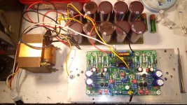
SARA 2016 V.1 tested ,and work very well
Beautiful board! Requires a proper compartment
Xrk971, there is a headphone driver chip - PT2308 - which specifically designed to drive headphones. Very low noise and very low distortion. But it requires a regulated 5V SE supply. Oatley Electronics, here in Oz, make a kit - K272 - which features the chip and in the latest incarnation has a 5V reg on board. But only in thier latest design.
Your efforts may well exceed the kit but for a low current drain, cool running headphone amp it is hard to go past for about AU$40.
Your efforts may well exceed the kit but for a low current drain, cool running headphone amp it is hard to go past for about AU$40.
Xrk971, there is a headphone driver chip - PT2308 - which specifically designed to drive headphones. Very low noise and very low distortion. But it requires a regulated 5V SE supply. Oatley Electronics, here in Oz, make a kit - K272 - which features the chip and in the latest incarnation has a 5V reg on board. But only in thier latest design.
Your efforts may well exceed the kit but for a low current drain, cool running headphone amp it is hard to go past for about AU$40.
Thanks for the tip. Do you have a link? I remain skeptical that an IC opamp can measure and sound like this simple 2H and very small H3 harmonic profile. I think this will just sound better and more direct than having a forest of harmonic content (even though low in absolute value). The amp needs to be single ended to have this profile I think. Most opamps have differential long tail pair inputs which cannot look like this.
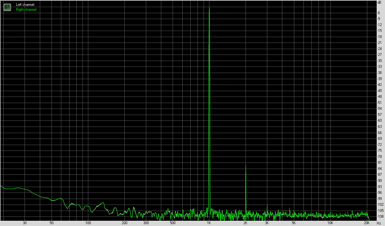
Can an opamp do this? I don't mind the heat - what's a few watts of dissipation between friends
Thanks for the tip. Do you have a link? I remain skeptical that an IC opamp can measure and sound like this simple 2H and very small H3 harmonic profile. I think this will just sound better and more direct than having a forest of harmonic content (even though low in absolute value). The amp needs to be single ended to have this profile I think. Most opamps have differential long tail pair inputs which cannot look like this.
Can an opamp do this? I don't mind the heat - what's a few watts of dissipation between friends
http://www.mouser.com/ds/2/405/tpa6120a2-556690.pdf. I've never listened to this one (can't use headphones) but it's supposed to be very good. IC amps aren't nearly as much fun to build as discrete amps though.
Thanks Jeff. CFA class AB amp with low odd order HD for $6ea.
TPA6120A2DWPG4 Texas Instruments | Integrated Circuits (ICs) | DigiKey
TPA6120A2DWPG4 Texas Instruments | Integrated Circuits (ICs) | DigiKey
That's a measurement I have never done.
Looks like the tiny blip after equallising the voltage of the in/out is the phase delay of the out vs the in.
Does anyone agree?
What happens if you use the horizontal expand by 10?
Can you see where the blip coincides, near the beginning of the rise, or near the end?
Hi Andrew,
I finally got around to upload another screen shot. You wanted to know what happens when dialing in a different time base. Hera ya go.
In this screen shot, I had used a steeper rise time pulse for the input signal, about 1us rise / fall time. Also I increased the amplitude to load the amp a little more.

It looks as though it is simply a phase delay affecting the output signal.
The peak of the blip happens to coincide with reaching the maximum of the input signal.
Thanks for taking the time to look at that and post a report.
Np, my pleasure.
Meanwhile over in freaky Germoney a hyping review hit youtube of a Bryston B9 SST2 selling at a lame 9000 Euros or so that can barely do 3.5us rise / fall time and I am sure it finds happy audiophile customers at that price.

Resistor value, your post now has a new thread of its own. This one is just for pictures of diy builds mainly.
New thread is here.
http://www.diyaudio.com/forums/solid-state/302668-audiolab-8000p-coffee.html

kct, it looks good!
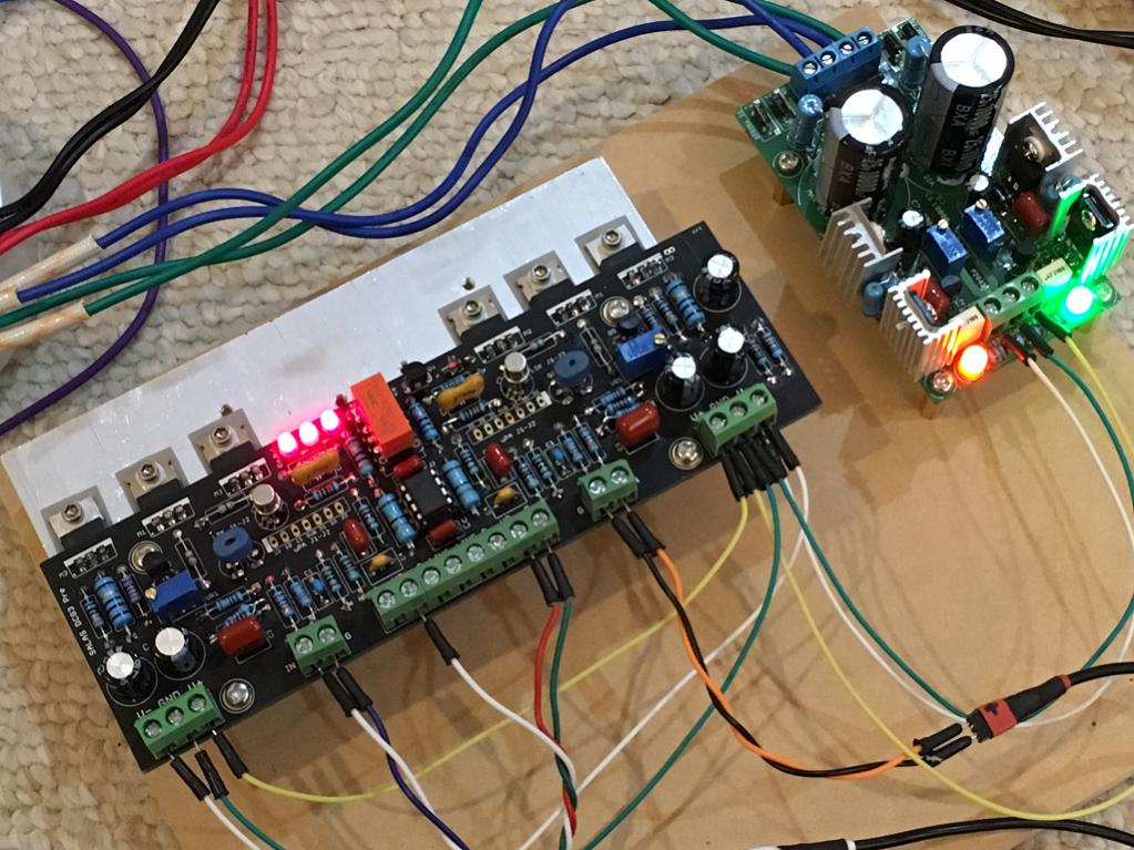
Your output inductor looks about 1.8uH, right? I believe the rise and fall times are pretty much dependent on the output inductor and its damping resistor. I'm under correction, but if the damping isn't enough, then you risk oscillation on some loads. Yours looks slightly underdamped, perhaps just enough. If you increase the output inductance slightly, and your rise and fall times increased to, say, 3.5us, but the amp is predictably much more stable, what of it? Will the amplifier not still be in a >50kHz spec?
Just curious.
kct, it looks good!
Your output inductor looks about 1.8uH, right? I believe the rise and fall times are pretty much dependent on the output inductor and its damping resistor. I'm under correction, but if the damping isn't enough, then you risk oscillation on some loads. Yours looks slightly underdamped, perhaps just enough. If you increase the output inductance slightly, and your rise and fall times increased to, say, 3.5us, but the amp is predictably much more stable, what of it? Will the amplifier not still be in a >50kHz spec?
Just curious.
Hi Mrcloc,
Thanks
, yes, you are right the inductor is about 1.8uH, I believe pretty much the same as the original amplifier had and within the usual range of 0.5 - 5uH as B. Cordell suggest. D. Self finds a common inductance of about 2.3uH as adequate for most designs. So I guess this may be close enough. Perhaps I will do a little more testing.So far I have not noticed any tendency for oscillation whatsoever, needlesse to say I am quite pleased with that, this thing seems very well if not exceptionally well behaved.
The original Spec. of this amp is DC - 200kHz @-3dB
The chief engineer at Technics 1985 undoubtedly knows his stuff.

Hi Mrcloc,
Thanks
So far I have not noticed any tendency for oscillation whatsoever, needlesse to say I am quite pleased with that, this thing seems very well if not exceptionally well behaved.
The original Spec. of this amp is DC - 200kHz @-3dB
The chief engineer at Technics 1985 undoubtedly knows his stuff.
Fantastic!

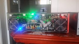
Silicon chip Ultra Ld Mk3 in an acrylic (Perspex) enclosure, yes it does work, but keep source device and speakers a distance away. Looks cool and sounds great
That does look cool.
I like it. It gives the techno look alright when one can see some of the guts inside.But my curiosity, what is the bright green light ? General illumination of the circuitry inside ? It seems very bright.
Cheers
- Home
- Amplifiers
- Solid State
- Post your Solid State pics here