Sure, but hope not soluble. Would not look good beside that beautiful amp.
That was a good coffee. Not "Espresso" but I like the size of this cup
Lasts long enough observation
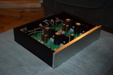
While you're still in the good mood, why the blue piggy-back processor board ?
Easier to have a separate one for smd, or something generic ?
While you're still in the good mood, why the blue piggy-back processor board ?
Easier to have a separate one for smd, or something generic ?
This is an old design of my "21-st century" control board - just had to use it somewhere. Current design is much more compact and ATmega328 as a separate chip - thanks to great contribution of Jeff Wilhelm to the control/protection board project
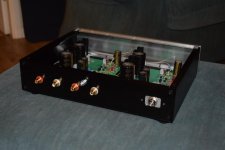
finished Jean Hiraga Super Class A amplifier@36w@1.65A bias
Hello my dear colleagues,
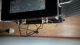
I can now proudly present, after one year of construction at this amp and allot of hours of labour for the case, wiring, listening tests... I had to say that I tested approx all the possible variants of components, and wiring (wire gauge, earthing, and cable managemnt),except for the regulated psu, Kubota regulated psu mod for input and CLC mode for output. ( keep these mods for later upgrade)...
Here are the specs:
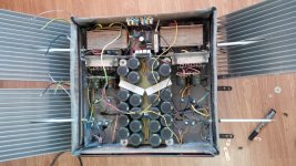
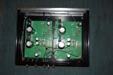
1. Two 300w trafos, bicafillar winded (equal impedance on both rails) ,custom made, one for each channel.
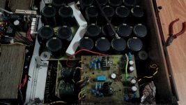
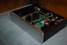
2. Ultrafast soft recovery high voltage high current diodes + 484000 uF filtering (22 pcs of 22000uF/35v for each channel CRC): 66000uF+0.22ohm/30w+176000uF/35v //per rail
3.Four small 10 w paralleled secondaryes for equal impedance, two per channel giving 20 w of juice just for the input.
4. Ultrafast soft recovery low voltage low current diodes + CRCRC psu for the input psu : 10000uF/35v+2*1ohm/3w paralelld resistors+ 10000uF/35v+ 3*1ohm/3w paralelld resistor + 2*1000uF+1*680uf low resistance Nichicon caps giving a total of 22680 uF per rail.
5. All of the components are matched on the amps within 1% passive components, 1% input trannies, 5% drivers and 8 % matching for outputs. I had chosen the drivers and outputs after listening to them in the long listening and exhausting session nights, and from 5 different series of outputs and drivers with different cobs, ft, and Pd's (on semiconductors, sanken, toshibas).
6. The amp receives 23vcc for the input stage and 27.2 vcc for the output on each channel, and a bias of 1.65 A idle current (sounds way relaxed and better at this current) and its outputing on 1000hz sinusoidal signal 38w@8ohm sinus into dummi load at clip and 35w into my speakers with ease.. The idle stays rock sollid after 30 mins of varming up at 2mV on left and 4mV on right channel.
7. Soft start (diy audio version).
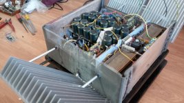
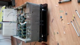
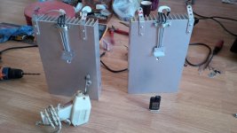
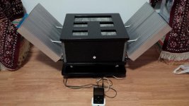
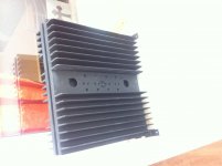
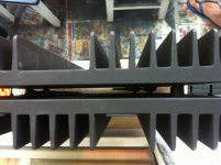
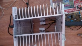
8. A big radiator for each output, with no insulator between each output trannie and the rads, only Prolimatech silver thermal grease and the rads completely isolated from the chasis. As you can see they are optimally oriented with the fins up and trannies bellow for the best heat dissipation because I saw when you rise the bias on this amp the temp rises rapidely, fact wich made me change two sets of rads till now, and tgis is the third pair. The is allot of heat dissipation here and if you want a longer life for the oitputs you have to go with the biggest rads that you can find.
Now they are running at 48 degrees celsius per output trannie @ 19 degree ambient in the winter..
I think that the whole amp has aprox 30-35kilos and it is really hard to lift. It has wheels for moving.
Almost everithing is made from scratch.
I will open a new thread with all of my findings about this amp till now and about my choices for the different components.
Thank you all for the help to all of you : 6L6, ZenMode, Ovidiu, AlexxMM, and all the other colleagues from the Hiraga 20w amp thread who helped me with good advices and sugestions.
Cheers to you all.
Altought it hasnt got an audiophille music source, now its runing on ipod classic 5.5 @ wolfson dac chip and Rockbox moded, it still blows you away with its realism, sweetness, soundstage, bass, controll, dynamics,and level of details.
Cheers
Sergiu
Hello my dear colleagues,
I can now proudly present, after one year of construction at this amp and allot of hours of labour for the case, wiring, listening tests... I had to say that I tested approx all the possible variants of components, and wiring (wire gauge, earthing, and cable managemnt),except for the regulated psu, Kubota regulated psu mod for input and CLC mode for output. ( keep these mods for later upgrade)...
Here are the specs:
1. Two 300w trafos, bicafillar winded (equal impedance on both rails) ,custom made, one for each channel.
2. Ultrafast soft recovery high voltage high current diodes + 484000 uF filtering (22 pcs of 22000uF/35v for each channel CRC): 66000uF+0.22ohm/30w+176000uF/35v //per rail
3.Four small 10 w paralleled secondaryes for equal impedance, two per channel giving 20 w of juice just for the input.
4. Ultrafast soft recovery low voltage low current diodes + CRCRC psu for the input psu : 10000uF/35v+2*1ohm/3w paralelld resistors+ 10000uF/35v+ 3*1ohm/3w paralelld resistor + 2*1000uF+1*680uf low resistance Nichicon caps giving a total of 22680 uF per rail.
5. All of the components are matched on the amps within 1% passive components, 1% input trannies, 5% drivers and 8 % matching for outputs. I had chosen the drivers and outputs after listening to them in the long listening and exhausting session nights, and from 5 different series of outputs and drivers with different cobs, ft, and Pd's (on semiconductors, sanken, toshibas).
6. The amp receives 23vcc for the input stage and 27.2 vcc for the output on each channel, and a bias of 1.65 A idle current (sounds way relaxed and better at this current) and its outputing on 1000hz sinusoidal signal 38w@8ohm sinus into dummi load at clip and 35w into my speakers with ease.. The idle stays rock sollid after 30 mins of varming up at 2mV on left and 4mV on right channel.
7. Soft start (diy audio version).
8. A big radiator for each output, with no insulator between each output trannie and the rads, only Prolimatech silver thermal grease and the rads completely isolated from the chasis. As you can see they are optimally oriented with the fins up and trannies bellow for the best heat dissipation because I saw when you rise the bias on this amp the temp rises rapidely, fact wich made me change two sets of rads till now, and tgis is the third pair. The is allot of heat dissipation here and if you want a longer life for the oitputs you have to go with the biggest rads that you can find.
Now they are running at 48 degrees celsius per output trannie @ 19 degree ambient in the winter..
I think that the whole amp has aprox 30-35kilos and it is really hard to lift. It has wheels for moving.
Almost everithing is made from scratch.
I will open a new thread with all of my findings about this amp till now and about my choices for the different components.
Thank you all for the help to all of you : 6L6, ZenMode, Ovidiu, AlexxMM, and all the other colleagues from the Hiraga 20w amp thread who helped me with good advices and sugestions.
Cheers to you all.
Altought it hasnt got an audiophille music source, now its runing on ipod classic 5.5 @ wolfson dac chip and Rockbox moded, it still blows you away with its realism, sweetness, soundstage, bass, controll, dynamics,and level of details.
Cheers
Sergiu
Attachments
-
 IMG_20151003_105506.jpg712.6 KB · Views: 1,054
 -
 IMG_20150826_194938.jpg551.2 KB · Views: 1,011
 -
 IMG_20151003_105517.jpg650.4 KB · Views: 986
 -
 IMG_20151003_114050.jpg669.5 KB · Views: 932
 -
 IMG_20151020_214723.jpg578.4 KB · Views: 842
 -
 IMG_20151003_114042.jpg650.1 KB · Views: 260
 -
 IMG_20151003_105445.jpg640.9 KB · Views: 256
 -
 IMG_20151003_114126.jpg603.8 KB · Views: 331
 -
 IMG_20151013_225803.jpg613.6 KB · Views: 427
 -
 IMG_20151011_194005.jpg582.3 KB · Views: 288
Hello my dear colleagues,
I can now proudly present, after one year of construction at this amp and allot of hours of labour for the case, wiring, listening tests... I had to say that I tested approx all the possible variants of components, and wiring (wire gauge, earthing, and cable managemnt),except for the regulated psu, Kubota regulated psu mod for input and CLC mode for output. ( keep these mods for later upgrade)...
Here are the specs:
1. Two 300w trafos, bicafillar winded (equal impedance on both rails) ,custom made, one for each channel.
2. Ultrafast soft recovery high voltage high current diodes + 484000 uF filtering (22 pcs of 22000uF/35v for each channel CRC): 66000uF+0.22ohm/30w+176000uF/35v //per rail
3.Four small 10 w paralleled secondaryes for equal impedance, two per channel giving 20 w of juice just for the input.
4. Ultrafast soft recovery low voltage low current diodes + CRCRC psu for the input psu : 10000uF/35v+2*1ohm/3w paralelld resistors+ 10000uF/35v+ 3*1ohm/3w paralelld resistor + 2*1000uF+1*680uf low resistance Nichicon caps giving a total of 22680 uF per rail.
5. All of the components are matched on the amps within 1% passive components, 1% input trannies, 5% drivers and 8 % matching for outputs. I had chosen the drivers and outputs after listening to them in the long listening and exhausting session nights, and from 5 different series of outputs and drivers with different cobs, ft, and Pd's (on semiconductors, sanken, toshibas).
6. The amp receives 23vcc for the input stage and 27.2 vcc for the output on each channel, and a bias of 1.65 A idle current (sounds way relaxed and better at this current) and its outputing on 1000hz sinusoidal signal 38w@8ohm sinus into dummi load at clip and 35w into my speakers with ease.. The idle stays rock sollid after 30 mins of varming up at 2mV on left and 4mV on right channel.
7. Soft start (diy audio version).
8. A big radiator for each output, with no insulator between each output trannie and the rads, only Prolimatech silver thermal grease and the rads completely isolated from the chasis. As you can see they are optimally oriented with the fins up and trannies bellow for the best heat dissipation because I saw when you rise the bias on this amp the temp rises rapidely, fact wich made me change two sets of rads till now, and tgis is the third pair. The is allot of heat dissipation here and if you want a longer life for the oitputs you have to go with the biggest rads that you can find.
Now they are running at 48 degrees celsius per output trannie @ 19 degree ambient in the winter..
I think that the whole amp has aprox 30-35kilos and it is really hard to lift. It has wheels for moving.
Almost everithing is made from scratch.
I will open a new thread with all of my findings about this amp till now and about my choices for the different components.
Thank you all for the help to all of you : 6L6, ZenMode, Ovidiu, AlexxMM, and all the other colleagues from the Hiraga 20w amp thread who helped me with good advices and sugestions.
Cheers to you all.
Altought it hasnt got an audiophille music source, now its runing on ipod classic 5.5 @ wolfson dac chip and Rockbox moded, it still blows you away with its realism, sweetness, soundstage, bass, controll, dynamics,and level of details.
Cheers
Sergiu
Attachments
Venar,
are you in the right Thread?
I thought the same thing when I saw Sergiu's amp.
Venar,
are you in the right Thread?
yes,of course!
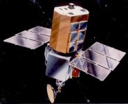
a satellite solar design amp(in my ayes)!
I thought the same thing
I better not show my class A-erofoil amp design for the tropics (90F/90RH) then.
I better not show my class A-erofoil amp design for the tropics (90F/90RH) then.
I like different designs for amp chassis. That one just reminded me of a satellite as soon as I saw it.
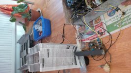
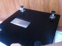
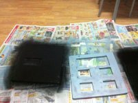
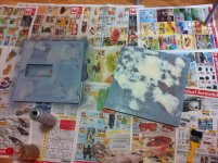
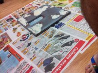
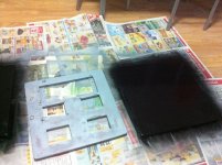
Thank you very much form the apreciation. It took me 4 months to do the amp and 8 months for the chasis. To be honest this is the third chasis design, the first had two big black radiators on the sides, and all the chassis was black and simple, nothing fancy, but after discovering the huge amount of heat dissipated by the trafos , drivers, output resistors, and the other components i changed the whole design to wood (second design), drill it, molde it, paint it in glossy black with two layers of laqueur and sanded from 800 up to 2000 grit sanding-paper and water after each layer of paint and laquer till i obtained an almost piano mirror finish, for the base, the top and the suport.
I cranked up the bias from 1.5 to 1.65 A and discovered a huge difference in finess, details, clarity, soundstage and voice relax (voices and instruments) so i wanted to stay there. With this modification the temp rised from 58 to a wopping 75 degree celsius for the output...
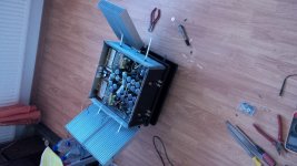
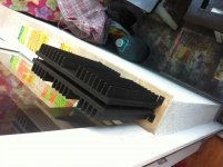
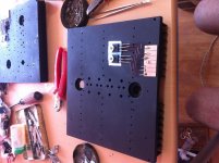
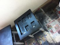
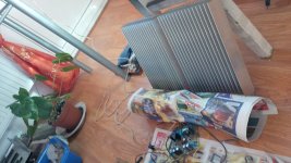
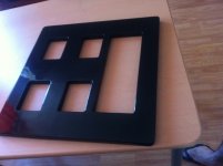
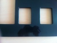
I needed to take quick measures for this problem so i adopted the "stack effect" or "horn effect" (its the same), and putted the two radiators face to face and modified the top plate, ruined it, from 6 square wholes i made four wholes and a big hole for the two radiators to say on the top of the chasis in "stack effect mode". The stack effect lowered the temps from 75 to 68~69~70 degrees.
I wasnt too happy about it so i rised some money, studyied allot from the net about heat dissipation, and buyied myself four radiators and this doubled the dissipation surface area for each transistor+ this time i didnt used mica insulation anymore, I made direct contact between the trannies and the rads and isolated the rads form the chasis. I also changed the classic silicium grease to Prolimatech silver grease this lowered the temp with 4 degrees..
After some days of experiments on the bench i found that this position of the rads that i have now loweres the temps even more, to be honest with aprox 10 degress celsius (i'm not kidding)..
So as you see here the desperate need for colling made me adopt this spatial like design. After this solution i resprayed the top and again all the above steps...
Here are some pics from my construction and tests.
Conclusions are that you should take serious measures when considering making a class A amp, and even more measures when biasing even further.. But what the heck, the sound is worth it.. As we speak i'm enjoying some Chris Rhea, Julio Iglesias, Diana Krall and some fast vocal trance music and some good wine with my wife.
Cheers to you all.
Sergiu
I cranked up the bias from 1.5 to 1.65 A and discovered a huge difference in finess, details, clarity, soundstage and voice relax (voices and instruments) so i wanted to stay there. With this modification the temp rised from 58 to a wopping 75 degree celsius for the output...
I needed to take quick measures for this problem so i adopted the "stack effect" or "horn effect" (its the same), and putted the two radiators face to face and modified the top plate, ruined it, from 6 square wholes i made four wholes and a big hole for the two radiators to say on the top of the chasis in "stack effect mode". The stack effect lowered the temps from 75 to 68~69~70 degrees.
I wasnt too happy about it so i rised some money, studyied allot from the net about heat dissipation, and buyied myself four radiators and this doubled the dissipation surface area for each transistor+ this time i didnt used mica insulation anymore, I made direct contact between the trannies and the rads and isolated the rads form the chasis. I also changed the classic silicium grease to Prolimatech silver grease this lowered the temp with 4 degrees..
After some days of experiments on the bench i found that this position of the rads that i have now loweres the temps even more, to be honest with aprox 10 degress celsius (i'm not kidding)..
So as you see here the desperate need for colling made me adopt this spatial like design. After this solution i resprayed the top and again all the above steps...
Here are some pics from my construction and tests.
Conclusions are that you should take serious measures when considering making a class A amp, and even more measures when biasing even further..
But what the heck, the sound is worth it.. As we speak i'm enjoying some Chris Rhea, Julio Iglesias, Diana Krall and some fast vocal trance music and some good wine with my wife.Cheers to you all.
Sergiu
Attachments
-
 IMG_3178.jpg442.3 KB · Views: 926
 -
 IMG_3175.jpg602.2 KB · Views: 983
 -
 IMG_3176.jpg501.9 KB · Views: 1,024
 -
 IMG_3179.JPG971.7 KB · Views: 881
 -
 IMG_3180.jpg466.4 KB · Views: 835
 -
 IMG_20150721_185947.jpg672.2 KB · Views: 307
 -
 IMG_20150721_185958.jpg554 KB · Views: 376
 -
 IMG_20150721_190030.jpg557.5 KB · Views: 376
Last edited:
Here are some other pics from the painfull process of painting. Enjoy.
Attachments
I better not show my class A-erofoil amp design for the tropics (90F/90RH) then.
Cant wait to see it. Show us Jacco.
- Home
- Amplifiers
- Solid State
- Post your Solid State pics here