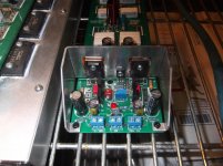
For the specific circuit which is a rather complicated issue since its a CFP But i run the vbe multiplier in different way than is originally designed .
There is a common heatsink for both of the drivers and vbe multiplier senses there
In the given enclosure and specific heatsink and taken as a fact that the work shop is air conditioned there is a variation of the bias of 15% between summer and winter
I was concerned about that and i have been monitoring this through a period of time to ensure that i walk within a reasonable level .
Kind regards
Sakis
Totally agree with the upgrade point. The OEM might not be specifically enginneered
to make the best use of a multiturn.
They most likely have a fixed series resistor that is slightly under the optimum bias ,
and just trim out a safe 10-100ma with a single turn pot. Everything is specifically
engineered for a set Ivas , drivers , and outputs.
When you specifically design around either a 10 or 25 turn , things are different.
On both the Badger and Slew , half the turns do nothing - the other half (5 or 12)
are either 8 or 30 ma per turn. Middle of the trimmer (250R) is usually the
(BJT) OPS conduction point.
As both OPS's are universal , having a greater range is beneficial to accommodate
different VAS currents and output devices. Once you hit that halfway point ,8-30ma
per turn is quite ideal. If you either choose to run a 8-10ma VAS (or are testing a prototype) ,
it might be absolutely essential to have 1/2 of those turns "extra" . On the slew ,
3.2ma to almost 12ma VAS will give an acceptable bias trim range.
The optimum is a 5-6ma Ivas.
With a vertical FET OPS , the same 25 turn trimmer will do >20ma per turn , I'd
rather have the higher resolution for a VFET's " hairy" conduction threshold .
OS
Hi Pete,
The padding resistors can change from version to version. It sounds as if the current implementation could use some padding resistors as well, then you could use more of the range of the control without such a severe sensitivity per turn. This is the entire point of going to a multi-turn control.
I am thinking of building the Honey Badger (just 'cause) and saw those damn 10 turn controls. I like the reports on this amplifier and have built the SymAsym, and I have some boards for Roender's version that I have yet to complete. The Slewmaster also sounds like an interesting amplifier to build.
-Chris
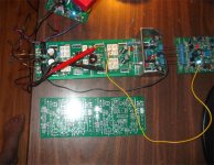
I have the new symasym (below small board), chris. Same compensation options but
with a servo and "fancy" cascoded wilson CM VAS.
This sym loves to belt out 140V p-p waveforms.
(below - big board) is the {new} V3 slewmaster EF3 , able to handle 5 pair ! MT-200
sanken output devices. The 30ma / per turn was with IRFP240/9240 , the new
boards can also use 5 pair of them (by popular demand).
I'm more conservative , just 5 pair MT-100's for me .
.
The OPS I have now does 10ma per turn , set it at 60ma 180 days ago , just
measured 59ma (it's a lot hotter now 38C in tennessee).
OS
with a servo and "fancy" cascoded wilson CM VAS.
This sym loves to belt out 140V p-p waveforms.
(below - big board) is the {new} V3 slewmaster EF3 , able to handle 5 pair ! MT-200
sanken output devices. The 30ma / per turn was with IRFP240/9240 , the new
boards can also use 5 pair of them (by popular demand).
I'm more conservative , just 5 pair MT-100's for me
.The OPS I have now does 10ma per turn , set it at 60ma 180 days ago , just
measured 59ma (it's a lot hotter now 38C in tennessee).
OS
Attachments
NO !!!.........................When you specifically design around either a 10 or 25 turn , things are different.
On both the Badger and Slew , half the turns do nothing..............
the Vbias is directly affected by the VR resistance.
A small change in the VR creates a small change in Vbias.
Monitor Vbias. You will see that the Vbias does change when a 25T pot is turned from it's stop at either end. It is NOT inoperative over some of it's rotation (once it is off it's stop/clutch)
The drivers, (Base to Base voltage = Vbias) operate directly with the Vbias.
They electrically subtract 2 Vbe from Vbias and send that on to the output devices. If one cares to monitor the Base to Base voltage of the output pair (the bias voltage after the drivers have subtracted their 2 Vbe) you will see that these too vary from near zero to full ON.
But you must exceed the driver 2Vbe to see some voltage at the outputs.
now monitor the output after the output devices. These too subtract 2Vbe from the base to base output from the drivers.
If one cannot be bothered to measure Vbias and only measure the Vre of the outputs one sees Vbias minus 4Vbe. If Vbias is less than 4Vbe, then one sees an apparent lack of response in the Vre. That lack of response because one is choosing to measure Vbias at the wrong location does NOT equate to "...half the turns do nothing..."
Last edited:
No ? Once your Vbe voltage falls below 1.1V on the EF2 or 2.2V on the EF3 ,
further turns of the trimmer do nothing (to the outputs bias).
Those further turns will continue to collapse the Vbe as the semi conducts more ,
so it's still changing. Just the final outputs stop conducting.
 I was just speaking plainly .... most will just monitor the output Re's ,
where "nothings happening". We know the Vbe's shunt has to work at all times ,
or we have full conduction P-N and a whole lotta "magic smoke".
My tester amp has a 5V zener across the Vbe device to assure
no smoke even if I forget to hook up a VAS connection.
further turns of the trimmer do nothing (to the outputs bias).
Those further turns will continue to collapse the Vbe as the semi conducts more ,
so it's still changing. Just the final outputs stop conducting.
I was just speaking plainly .... most will just monitor the output Re's ,where "nothings happening". We know the Vbe's shunt has to work at all times ,
or we have full conduction P-N and a whole lotta "magic smoke".
My tester amp has a 5V zener across the Vbe device to assure
no smoke even if I forget to hook up a VAS connection.
Last edited:
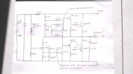
2N3055 Amplifier
Hi all. I built an amplifier based on 2N3055. I wanted to use 2N3055 transistors as I have a swag of them in TO3 form. I used this CCT below with some minor changes. I am also running it at +75 volts single supply rail. I wanted to use both NPN output transistors so this is why I used this CCT with a single supply rail. And also its simplicity! All other transistors are BD139/BD140 except the front small signal gain stage which is a BC559c. The amplifier works quite well with a continuous output of 50 watts RMS into 8 ohms and over 65 watts into 4ohms. Gain is set at 27db. For such a simple CCT I managed to get a distortion reading of about 0.07% at 50 watts RMS and down to 0.05% at all other power levels tested at 100, 1k and 10kHz frequencies . Here are some pics. Please note. I found this CCT on the web.The hand drawn CCT is mine. So I do not take any credit for it.
Regards
Billy D...
*****************
Attachments
Last edited:
Hi Pete,
I understand where you are coming from with your bias trim control's useful range. Just needs some pad resistors in series to lose those dead areas. Yes, you were talking about the change in bias as seen by the meter setting bias current.
The new SymAsym sounds interesting for sure. Can you PM with some details please? You have peaked my interest. I really want to hear some of your work first hand. There are some MJL21195 and MJL21196 transistors calling my name. They sitting here waiting for use in the build of one of your amplifiers. I don't require mega watts, so one or two pair per channel will be plenty.
One question. Can this output stage be used with BJT outputs? I imagine the answer is yes.
Pete, a little earlier in time, did you mention that you had boards to fit the Nikko Alpha 220 / 230 amplifiers? What amplifier & version were they for?
I looked upon the SymAsym as a utility amplifier, just a general use amplifier for applications that didn't require extreme sound quality. I have to say that I was surprised by the performance of this little amplifier by how good it is. Later these may find use in an active speaker system.
-Chris
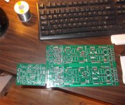
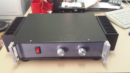
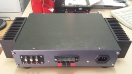
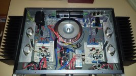
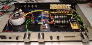
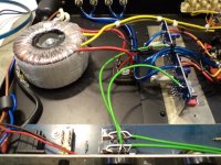
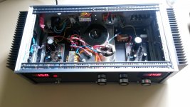
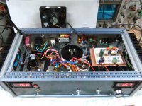
Surplus Magnum
Magnum IA 170 burned beyond repair as usual but i got to keep the enclosure for a few euro
So i made a surplus model
case burned magnum
Trafo from a broken DB technologies active monitor
Caps /relays from burned 7+1 Pioneer ( beyond ..any repair )
Pot from a Luxman surplus amplifier
LM 3886 x 2 from surplus Behringer monitor
Phono stage from broken Sansui A700
3 hours to make ....plays fine for a 3886 thingy
Attachments
Hi Pete,
I understand where you are coming from with your bias trim control's useful range. Just needs some pad resistors in series to lose those dead areas. Yes, you were talking about the change in bias as seen by the meter setting bias current.
The new SymAsym sounds interesting for sure. Can you PM with some details please? You have peaked my interest. I really want to hear some of your work first hand. There are some MJL21195 and MJL21196 transistors calling my name. They sitting here waiting for use in the build of one of your amplifiers. I don't require mega watts, so one or two pair per channel will be plenty.
One question. Can this output stage be used with BJT outputs? I imagine the answer is yes.
Pete, a little earlier in time, did you mention that you had boards to fit the Nikko Alpha 220 / 230 amplifiers? What amplifier & version were they for?
I looked upon the SymAsym as a utility amplifier, just a general use amplifier for applications that didn't require extreme sound quality. I have to say that I was surprised by the performance of this little amplifier by how good it is. Later these may find use in an active speaker system.
-Chris
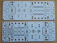
NO 21195/96 transistors !!! My amps are too fast for them (even the symasym).
Builder Thimios created cross conduction with a pair ,
blew em' up.
Edit - designer vzaichenko blew some up , too - his amps are too fast , as well.
Digikey has the sanken's for <5$ each -cheap , save the 21195's for
switching motors or something
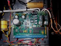
.Reason why ... is the fast predriver/driver (below 1) ,150mhz pre/ 60mhz driver
pair. Only 30mhz+ ON/Sanken's are good. With fast BJT's (or even
IRFP VFET's !) , this OPS will recreate the slower "symasui" ... (below 2-
with OPS) 80V/us all the way to a 200V/us fancy new CFA
module. I've seen an easy 250V/us and nice 200khz squarewaves out
of the Slewmaster.
The board pictured will take 3 or 5 pair mt-200/TO-3P/TO-264/IRFPxxxx.
Totally universal with no jumpering. 400W+ amps are possible.
Have almost a dozen input stages to go along with all that power.
Vzaichenkos "21'st century protection" integrates directly now (DC/current/
temperature - Below 3). Pass/Parasound level projects. No more BS.
OS
Attachments
Last edited:
Addition to my class A amplifier
Pure class A based on the "death of zen " 54 watts dissipation for 15 watts rms output into 8 ohms per channel. I have incorporated a pre amplifier made of miniature 6418 tubes which runs off the same power supply via a regulator. I found I did not have enough gain due to the amplifiers slightly lower than usual gain and also the passive balance control which i included which I lost much more gain than anticipated, so I made up this pre amp. The amplifier sounds more lively with plenty of volume. I have set the gain to 26dB. Incredibly the hum and noise is practically zero with proper routing of the power cables. Panel meters do not affect the amplifier at all with noise etc. I could of made a descrete solid state or even an op amp pre amp but I thought I would make a little different since I have some of these little tubes in my parts bin.
Regards
Billy D...
************************
Attachments
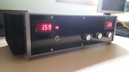
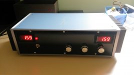
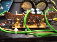
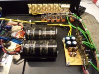
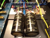
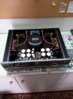
So proud to present one amplifier P3A that is made from a friend under my guidance PCB is made in cooperation , and in total amplifier features 8x10.000 ufd fast rectifiers slow start shielded transformer 500va analog VU meters with logarithmic drive and DC protection
Detailed pictures to come in the feature
So proud for "my boy "
Detailed pictures to come in the feature
So proud for "my boy "
Attachments
Hi Pete,
Okay, I haven't looked at these in a while. I suspect that is why they haven't been used yet! I just forgot and saw this nice pile of new transistors begging for a life.
I also have NJW series parts. The MJW0281A and MJW0302A are my favorite outputs, which is why there aren't many around here.
How do you find the MJL3281/MJL3302 parts? I should have a look at those specifications before asking really. I do thank you for the warning on the MJL21195/96 transistors. They should do well as regulators since they would always be biased on. Output caps take up the speed slack.
-Chris
So proud to present one amplifier P3A that is made from a friend under my guidance PCB is made in cooperation , and in total amplifier features 8x10.000 ufd fast rectifiers slow start shielded transformer 500va analog VU meters with logarithmic drive and DC protection
Detailed pictures to come in the feature
So proud for "my boy "
Looks great, shame you didn't have twins
this is my Danny40w power amp build...
An externally hosted image should be here but it was not working when we last tested it.
An externally hosted image should be here but it was not working when we last tested it.
An externally hosted image should be here but it was not working when we last tested it.
Hi AJT,
Very, very nice. Certainly one of the neater builds.
I have to admit, your current limiting light bulb looks great in the box. Otherwise you could suffer a blinding short if you weren't careful!
-Chris
Hi Chris, i did not want to throw the box away so might as well use it...
- Home
- Amplifiers
- Solid State
- Post your Solid State pics here