Hi kacernator,
Ahhh, no. The design is too simple. Its great that you like the sound of it, and I am sure it doesn't sound bad. Mosfet or BJT outputs need better drive than a simple tube circuit can muster. If this design is expanded on a little, you could really make it better by isolating the tube from the output stage.
Is there a relay circuit to only connect your speakers after the DC offsets have stabilized? For tubes, the delay will often run a couple minutes, at least one. This is for solid state output stages. Tube - transformer outputs can remain connected to the speakers as long as the amp is well behaved.
Is this your first amplifier build? If so, you have done a pretty good job with it. The one minor thing I would suggest to you is to use washers and lock washers between the nut and your output transistors - even with the TO-220 case style transistors on the heat sink. Make sure you don't over-tighten these your transistors. Most people starting out do.
Please take my comments as constructive. I think you did a decent job putting the amplifier together.
-Chris
Hi Chris,
design is absolutely fine. Look up IOTA-CD amplifier by Dr. Borivoje Jagodic.
Ofcourse DC relay connects speakers after everything is stabilized, and it takes just about 15 seconds. Amplifier uses DC servo.
Attachments
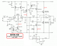
Cool , drivers are current sourced ... which keeps OP bias stable until
the valve stabilizes.
One step beyond -
Vzaichenko's hybrid-http://www.diyaudio.com/forums/solid-state/262450-ultra-high-performance-yet-rather-simple-hybrid-more.html
... uses 3 stages with the valve on the 1'st. red led
Vf keeps VAS current stable here (until the valve stabilizes).
Just the old Sansui 3-stage with a Valve instead of Jfet's.
ALL of Dr. Borivoje Jagodic's designs are rock stable with solid engineering
behind them. My studies involved his designs to gain my present level of
understanding. He's "the man" (for amp design).
OS
the valve stabilizes.
One step beyond -
Vzaichenko's hybrid-http://www.diyaudio.com/forums/solid-state/262450-ultra-high-performance-yet-rather-simple-hybrid-more.html
... uses 3 stages with the valve on the 1'st. red led
Vf keeps VAS current stable here (until the valve stabilizes).
Just the old Sansui 3-stage with a Valve instead of Jfet's.
ALL of Dr. Borivoje Jagodic's designs are rock stable with solid engineering
behind them. My studies involved his designs to gain my present level of
understanding.
He's "the man" (for amp design).OS
I wasn't suggesting that Andrew was 'wrong', just that, like many topics and solutions within these forums there are often contradictory solutions. Separating the wheat from the chaff is often difficult - depending upon whom you choose to believe.Hi redjr,
Andrew is correct here, and it doesn't help that many commercial designs get this wrong. Examples include the Marantz 500 and the Nakamichi "HTA" series receivers. I understand why Marantz did this, but in a receiver it puzzles me a bit.
You can include a buffer in your power amplifier input if it might be driven by sources without good drive capability. You absolutely need a buffer on the outputs of preamplifiers, phono preamps and preamplifiers. The power amp is optional.
-Chris
There has to be a practical solution for DIY'ers without having to build an external box just to contain a buffer - especially when no other preamp is used and only a single source is used.
Where do you then place the volume control? As any number of our wonderful forums exhibit, I've seen hundreds, if not thousands of DIY amps with and without volume controls.
I'm still trying to reconcile Andrew's statement:
"Because it forces you to place the Source close to the Receiver.
That in turn places the volume control next to the speakers, or excessively long speaker cables."
What does he mean, 'places the volume control next to the speakers'? And why does that necessarily imply long speaker runs? If my scenario is described as below;
SOURCE > (short interconnects) > BUFFER > (very short interconnects <6") > AMP > (short speaker cables) > SPEAKERS.
If I have very short <6" interconnects from the BUFFER(w/VC) to the AMP, why would it matter (practical sense), where the BUFFER physically resides?
Simply put: What is audio's 'best practice' here, especially when so many commercial integrated amps get it wrong!
Rick
I wasn't suggesting that Andrew was 'wrong', just that, like many topics and solutions within these forums there are often contradictory solutions. Separating the wheat from the chaff is often difficult - depending upon whom you choose to believe.
There has to be a practical solution for DIY'ers without having to build an external box just to contain a buffer - especially when no other preamp is used and only a single source is used.
Where do you then place the volume control? As any number of our wonderful forums exhibit, I've seen hundreds, if not thousands of DIY amps with and without volume controls.
I'm still trying to reconcile Andrew's statement:
"Because it forces you to place the Source close to the Receiver.
That in turn places the volume control next to the speakers, or excessively long speaker cables."
What does he mean, 'places the volume control next to the speakers'? And why does that necessarily imply long speaker runs? If my scenario is described as below;
SOURCE > (short interconnects) > BUFFER > (very short interconnects <6") > AMP > (short speaker cables) > SPEAKERS.
If I have very short <6" interconnects from the BUFFER(w/VC) to the AMP, why would it matter (practical sense), where the BUFFER physically resides?
Simply put: What is audio's 'best practice' here, especially when so many commercial integrated amps get it wrong!
Rick
I think AndrewT's point was the source, buffer and volume control are all sensitive to EMI and other noise produced heavily by the amplifiers and speaker cabling. It's best to keep them as far apart as reasonably possible.
without a an output stage that can drive long cables we are all consigned to using short cables.
That puts the source near the vol pot.
And puts the vol pot near the amplifier.
and puts the amplifier near the speaker.
That restricts operability.
We need longer cables somewhere.
The easiest is longer interconnects between the Buffer and the amplifier.
Then we can locate the source near the switcher, near the vol pot, near the Buffer. Then longer interconnects from the Buffer to the amplifiers which are near the speakers.
That uses just one stereo buffer at the output of the vol pot. The vol pot in this situation is the Source. The vol pot is the Source that cannot drive long cables.
My "pitchfork" preamp will have the line buffer included (below).
With -200db PSRR and 1ppm THD20 , I would never throw it in
with my "slewmaster" power amp.
It would not take much EMI or inductive coupling to degrade those specs.
Plus , the 10 ohm output impedance will assure even poor interconnects
will perform.
OEM "integrated amps" often include a pre-buffer to accommodate the wide
array of inputs - but this is a separate "pro" system - not OEM consumer fare.
OS
Hi OS,
Any plans on balanced design? PCB group buy?
Thanks
Do
As with "all good things" , they must be built , debugged , refined.
It took days to just find the right low noise solution (on mars) ...
mars probe "wenzel" tech. To create a piece of fine instrumentation
requires researching the "commonplace" , to set higher goals.
The Badger was a 2008 - 2011 ongoing project before it became DIYA's
amp.
PS - the "pitchfork" won't take 3 years , but I'm being real "anal" with it.
OS
It took days to just find the right low noise solution (on mars
) ...mars probe "wenzel" tech. To create a piece of fine instrumentation
requires researching the "commonplace" , to set higher goals.
The Badger was a 2008 - 2011 ongoing project before it became DIYA's
amp.
PS - the "pitchfork" won't take 3 years , but I'm being real "anal" with it.
OS
So.... Is it fair to say (or not), that a well-designed active preamp (by definition) will include a buffer stage suitable enough to drive long interconnects to the amp? Or, is that just an assumption on my part as to what a preamp does? Maybe it would help to define what is 'long' in our context here. 6' or 18'?without a an output stage that can drive long cables we are all consigned to using short cables.
That puts the source near the vol pot.
And puts the vol pot near the amplifier.
and puts the amplifier near the speaker.
That restricts operability.
We need longer cables somewhere.
The easiest is longer interconnects between the Buffer and the amplifier.
Then we can locate the source near the switcher, near the vol pot, near the Buffer. Then longer interconnects from the Buffer to the amplifiers which are near the speakers.
That uses just one stereo buffer at the output of the vol pot. The vol pot in this situation is the Source. The vol pot is the Source that cannot drive long cables.
So.... Is it fair to say (or not), that a well-designed active preamp (by definition) will include a buffer stage suitable enough to drive long interconnects to the amp? Or, is that just an assumption on my part as to what a preamp does? Maybe it would help to define what is 'long' in our context here. 6' or 18'?
I want to drive 12' quality cables. 10R Z should do it. Some digital sources
also might need a bit more gain. My CD will drive my big amp (all the way).
My sound card won't. It helps to have more than 1:1 gain in a buffer to
equalize different sources.
I can keep my DAC/buffers/attenuation away from anything else , shield
the trafo .... even build a partial faraday cage around it. Super shielded
and dead quiet. Real hard to do this in the "big amp" - all that industrial
AC wiring , relays .... huge trafo's !
The buffer (being discrete), can also easily drive headphones and
12' cables , driving the big amp all the time (all the way) might get the cops called !
OS
driving the big amp all the time (all the way) might get the cops called !
Not to mention, ruining what's left of your hearing.
SONIC Amp Photos by oscillator2 | Photobucket
To investigate further and not spam the topic, click the photobucket link for more photo's
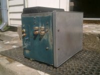
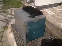
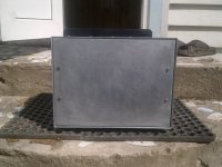
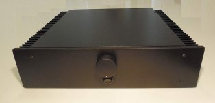
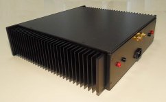
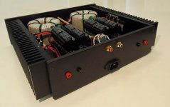
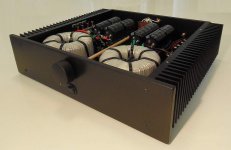
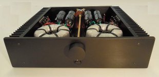
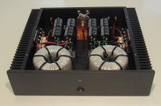
Started it yesterday and did hurt my back by lifting it off the ground to the table, completely silent if Laptop is turned off while RCA's are connected.
Biased to 30mA each channel, @ 25C room temperature without cables attached to amp. Sound wise, it has potential
To investigate further and not spam the topic, click the photobucket link for more photo's
Started it yesterday and did hurt my back by lifting it off the ground to the table, completely silent if Laptop is turned off while RCA's are connected.
Biased to 30mA each channel, @ 25C room temperature without cables attached to amp. Sound wise, it has potential
Attachments
8 Channel APEX A-14 amp finished, sound awesome.
An externally hosted image should be here but it was not working when we last tested it.
An externally hosted image should be here but it was not working when we last tested it.
An externally hosted image should be here but it was not working when we last tested it.
An externally hosted image should be here but it was not working when we last tested it.
An externally hosted image should be here but it was not working when we last tested it.
An externally hosted image should be here but it was not working when we last tested it.
An externally hosted image should be here but it was not working when we last tested it.
An externally hosted image should be here but it was not working when we last tested it.
An externally hosted image should be here but it was not working when we last tested it.
An externally hosted image should be here but it was not working when we last tested it.
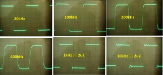
- topolgy: (advanced) symasym
- PS: 2 x 300VA trafo, 2 x 2 x 40mF 60V
- OPS: 3P devices
- chassis: painted MDF
- measurements: attached
- sound: 's cool...
Attachments
Hi Rick,
-Chris
Like so many other things in life, the best practice is what we have been doing for decades. The length of the speaker cable is not important given that the wire gauge is suited for the power level and distance. That's it, that's all.I wasn't suggesting that Andrew was 'wrong', just that, like many topics and solutions within these forums there are often contradictory solutions. Separating the wheat from the chaff is often difficult - depending upon whom you choose to believe.
There has to be a practical solution for DIY'ers without having to build an external box just to contain a buffer - especially when no other preamp is used and only a single source is used.
Where do you then place the volume control? As any number of our wonderful forums exhibit, I've seen hundreds, if not thousands of DIY amps with and without volume controls.
I'm still trying to reconcile Andrew's statement:
"Because it forces you to place the Source close to the Receiver.
That in turn places the volume control next to the speakers, or excessively long speaker cables."
-Chris
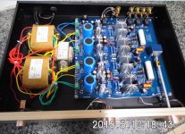
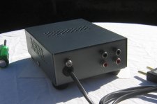
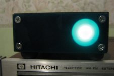
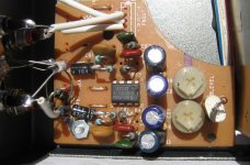
RIAA phono preamplifier from scrap parts
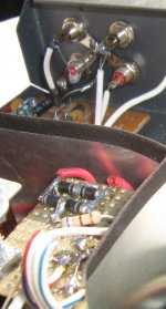
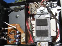
A communications device metal box, and a tape head amplifier board (from an old cassette player) plus some paint work and an acrylic front plate, repurposed as a nice RIAA phono pramplifier...

A communications device metal box, and a tape head amplifier board (from an old cassette player) plus some paint work and an acrylic front plate, repurposed as a nice RIAA phono pramplifier...
Attachments
with mods de-rigeur, off course...a tape head amplifier board (from an old cassette player) ]
... and a tape head amplifier board (from an old cassette player) ..... repurposed as a nice RIAA phono pramplifier...
That part is just so wonderful
- Home
- Amplifiers
- Solid State
- Post your Solid State pics here