Yes, Thimios: it is!
A LDR-based attenuation (like the one that I am currently using myself - see image above) - is great!
But: I will substitute the stereo ALPS - 100K analog stereo potentiometer by a digital MCP42100 one, being followed by a VCCS, and I am sure that this one will do a really nice (better) job as well!
Regards - Rudi
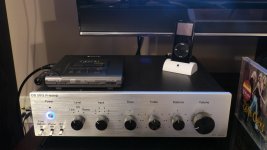
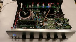
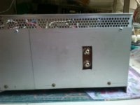
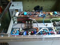
Good stuff Rudi. I need to decide on just how large of an enclosure I need to fit everything in your digital lineup for this 'integrated amp'. I'm not sure if a 4U standard rack width will suffice, or if I should go to a 5U with plenty of room! Either way, it will be $$$.Gentlemen, I would like and show you a picture of my current SYMASYM-build.
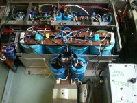
Most of the parts that you can see on the attached pictures are "DIYed".
The case has been built by my carpenter-friend Gerhard.
The SYMASYM-integrated-amplifier consists of:
- two DUAL-Mono SYMASYM Black (Green!) - Beauty SYMASYM-PCBs
- Mains Schaffner-filter being followed by a mains-DC-filter and Soft-Power-On
- 4 x 25 VAC torroid transformer rated at 400VAC
- My VCPRe (doing the source selection, attenuation (via LDRs), .....)
- Every functionality can be controlled via a IRC - unit
This build is using the small SANKEN TO3-P output transistors 2SC3263/2SA1294, and the "Allegro-SANKENs" play "like a divine".
I am currently thinking about which INTERNET-interface to add to this amplifier to be able to listen to INTERNET-radio and which DAC and Multimedia-player-software to add to be able to listen to my 1TB of my ripped CDs.
Best regards - Rudi_Ratlos
") The DIY store sells a nice 5U, but it is mucho dollars too!
The DIY store sells a nice 5U, but it is mucho dollars too!Rick
Good stuff Rudi. I need to decide on just how large of an enclosure I need to fit everything in your digital lineup for this 'integrated amp'. I'm not sure if a 4U standard rack width will suffice, or if I should go to a 5U with plenty of room! Either way, it will be $$$.
Rick
4U ... 5U ??? This is not class A !!
I have a 1Kva , 100Kuf and 500 watts of amp in a 3U ! With room left over.
Even the class A genesis stealth was a 4U X 15" deep ( 2KW dissipation).
PS - rudy' s amp would play all day in death valley or the sahara - easy.
OS
It's not just for the amp OS. There are several modules in the works to be included in the end product. B1 buffer, VC-Pre, Raspberry Pi, DAC, 500VAC xformer, and couple smaller xformers. Just want to make sure I have enough room!4U ... 5U ??? This is not class A !!
I have a 1Kva , 100Kuf and 500 watts of amp in a 3U ! With room left over.
Even the class A genesis stealth was a 4U X 15" deep ( 2KW dissipation).
PS - rudy' s amp would play all day in death valley or the sahara - easy.
OS
Don't worry, I haven't purchased the enclosure yet. Still months away.Rick: to build a case that suits your needs, pleases your eyes and is much cheaper than the cases that are being offered: "DIY a case of your own!"
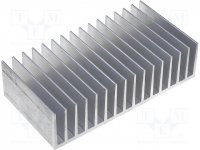
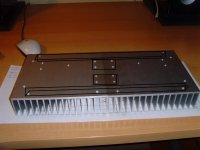
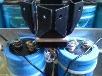
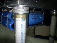
Buy a couple (4) of these (RAD-A6023/100 - Kühlkörper: geprägt | TME Germany GmbH - Electronic components) or similar heatsinks (size: 100 x 190.5mm - image 1)
and screw them together with some ALU-L profiles / ALU-plates (image 2 - I am no good at painting 3D - images!).
You can then go on with either ALU- or wooden bottom / top / rear / front plates - just the way you like it.
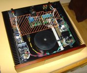
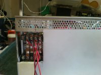
After you have finished / integrated your amplifier into this case: build a 2nd floor (image 3) and install the needed multimedia-components that you need:
(RASPBERRY PI, DAC, PSU, ...) onto the 2nd floor (which can be made of 2mm ALU or wood or ...).
It is so easy .... does not cost a lot, and you can give it the nicest wooden front that you can imagine.
Best regards - Rudi
Buy a couple (4) of these (RAD-A6023/100 - Kühlkörper: geprägt | TME Germany GmbH - Electronic components) or similar heatsinks (size: 100 x 190.5mm - image 1)
and screw them together with some ALU-L profiles / ALU-plates (image 2 - I am no good at painting 3D - images!).
You can then go on with either ALU- or wooden bottom / top / rear / front plates - just the way you like it.
After you have finished / integrated your amplifier into this case: build a 2nd floor (image 3) and install the needed multimedia-components that you need:
(RASPBERRY PI, DAC, PSU, ...) onto the 2nd floor (which can be made of 2mm ALU or wood or ...).
It is so easy .... does not cost a lot, and you can give it the nicest wooden front that you can imagine.
Best regards - Rudi
Attachments
Thanks for the suggestions Rudi. I probably won't use a 4U or larger case, but I go more for the professional finished look than DIY. I also prefer aluminum over wood, but that's just me. No offense to those that do.Rick: to build a case that suits your needs, pleases your eyes and is much cheaper than the cases that are being offered: "DIY a case of your own!"
Buy a couple (4) of these (RAD-A6023/100 - Kühlkörper: geprägt | TME Germany GmbH - Electronic components) or similar heatsinks (size: 100 x 190.5mm - image 1)
and screw them together with some ALU-L profiles / ALU-plates (image 2 - I am no good at painting 3D - images!).
You can then go on with either ALU- or wooden bottom / top / rear / front plates - just the way you like it.
After you have finished / integrated your amplifier into this case: build a 2nd floor (image 3) and install the needed multimedia-components that you need:
(RASPBERRY PI, DAC, PSU, ...) onto the 2nd floor (which can be made of 2mm ALU or wood or ...).
It is so easy .... does not cost a lot, and you can give it the nicest wooden front that you can imagine.
Best regards - Rudi
I also won't try and get the same level of compactness that I did with my Doug Self preamp build a couple of years ago. First image. But I do like the exterior finish of these re-made enclosures available from Asia. They're solid and with a little help from Front Panel Express, the front deck can be made to look very, very good and provide the finishing 'polish' to a project. Second image.
Anyway, I have much work still to do before deciding the correct size and the other modules you have planned for the multi-media, integrated amp. I try to take my time and plan everything out first. Of course there's always the 'as-built' component of this hobby too!
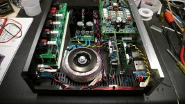
I think your size is perfect, but that was by design I'm sure. So, once all the pieces come together, the best size will reveal itself as I start to mock-up the layout. Somewhat similar to what you have done with a second horizontal deck in the enclosure. Finished interior - third image.
Rick
Attachments
Last edited:
The B1 Buffer does not belong inside the Power Amplifier.It's not just for the amp OS. There are several modules in the works to be included in the end product. B1 buffer, VC-Pre, Raspberry Pi, DAC, 500VAC xformer, and couple smaller xformers. Just want to make sure I have enough room!
If your Source needs a Buffer, then that Buffer should be at the output of the Source, not at the Receiver.
Last edited:
The B1 Buffer does not belong inside the Power Amplifier.
.
For my edification why is that?
A Source drives a Receiver.
There are two effects that need to be analysed.
a.) The filter effect of source impedance combined with capacitive loading.
b.) The voltage available over the full audio frequency range at the Receiver input.
The filter effect comes in three stages.
c.) the cable capacitance combined with the output resistance of the source gives a low pass filter.
d.) the RF attenuator fitted to the Receiver combined with the sum of the source resistance and the cable resistance gives a low pass filter
e.) the source inductance and the cable inductance combined with the Receiver RF attenuator adds a second pole to the two previous low pass filters.
The resistance/impedance of the Source affects both a&b.
A variable output impedance, within the audio band, at the Source will change the voltage at the Receiver even if the Receiver input load never changed. The 1:10 impedance ratio we regularly see recommended helps reduce the effects of variable source impedance and variable load impedance.
All the effects discussed above are reduced and can be made more predictable by ensuring that the Source output impedance is both low and not too variable. If the Source cannot achieve adequately low impedance then the easy solution is to add a Buffer that does have an adequately low output impedance. That low source impedance now drives the interconnect cable and the Receiver.
Putting the Buffer inside the Receiver helps a bit with b. but does virtually nothing for a, c, d & e.
The Buffer when required NEEDS to be at the start of the interconnect route, NOT at the end of that route.
A Source drives a Receiver.
There are two effects that need to be analysed.
a.) The filter effect of source impedance combined with capacitive loading.
b.) The voltage available over the full audio frequency range at the Receiver input.
The filter effect comes in three stages.
c.) the cable capacitance combined with the output resistance of the source gives a low pass filter.
d.) the RF attenuator fitted to the Receiver combined with the sum of the source resistance and the cable resistance gives a low pass filter
e.) the source inductance and the cable inductance combined with the Receiver RF attenuator adds a second pole to the two previous low pass filters.
The resistance/impedance of the Source affects both a&b.
A variable output impedance, within the audio band, at the Source will change the voltage at the Receiver even if the Receiver input load never changed. The 1:10 impedance ratio we regularly see recommended helps reduce the effects of variable source impedance and variable load impedance.
All the effects discussed above are reduced and can be made more predictable by ensuring that the Source output impedance is both low and not too variable. If the Source cannot achieve adequately low impedance then the easy solution is to add a Buffer that does have an adequately low output impedance. That low source impedance now drives the interconnect cable and the Receiver.
Putting the Buffer inside the Receiver helps a bit with b. but does virtually nothing for a, c, d & e.
The Buffer when required NEEDS to be at the start of the interconnect route, NOT at the end of that route.
Thank you for the detailed reply
A Source drives a Receiver.
There are two effects that need to be analysed.
a.) The filter effect of source impedance combined with capacitive loading.
b.) The voltage available over the full audio frequency range at the Receiver input.
The filter effect comes in three stages.
c.) the cable capacitance combined with the output resistance of the source gives a low pass filter.
d.) the RF attenuator fitted to the Receiver combined with the sum of the source resistance and the cable resistance gives a low pass filter
e.) the source inductance and the cable inductance combined with the Receiver RF attenuator adds a second pole to the two previous low pass filters.
The resistance/impedance of the Source affects both a&b.
A variable output impedance, within the audio band, at the Source will change the voltage at the Receiver even if the Receiver input load never changed. The 1:10 impedance ratio we regularly see recommended helps reduce the effects of variable source impedance and variable load impedance.
All the effects discussed above are reduced and can be made more predictable by ensuring that the Source output impedance is both low and not too variable. If the Source cannot achieve adequately low impedance then the easy solution is to add a Buffer that does have an adequately low output impedance. That low source impedance now drives the interconnect cable and the Receiver.
Putting the Buffer inside the Receiver helps a bit with b. but does virtually nothing for a, c, d & e.
The Buffer when required NEEDS to be at the start of the interconnect route, NOT at the end of that route.
Of these variables you mention, what are truly real world concerns and which are theoretical in nature. If your interconnects between the source and buffer are short (< 3'), are the cable capacitance and inductance of 'real' concern and enough to adversely affect the sound quality?
if your cable is <3' then you have immediately compromised your system operability.
Why do I say that?
Because it forces you to place the Source close to the Receiver.
That in turn places the volume control next to the speakers, or excessively long speaker cables.
In my view it is far easier to use longer interconnects and place the volume control where you need it.
This convenience restriction can be overcome by using multichannel remote controls that are located at each speaker. Gets quite/too complex for my abilities.
Back to your specific question: for cables <3', the parasitics are usually low if you adopt conventional cabling. This allows slightly higher Source impedance without sacrificing extreme treble. But you are still limited by the usual 1:10 ratio for source:receiver impedance. This is for item b. in post4030
I try for and easily achieve 1:20 ratio.
W.Jung shows the argument for adopting 50:>1M (1:20000) in some of his articles.
Last edited:
Not sure I understand all of what you just mentioned. Seems I need to do a little more research and understand what a buffer does and how best to connect/use it in a conventional setup, or with the numerous types of amps being built and shared in these forums.if your cable is <3' then you have immediately compromised your system operability.
Why do I say that?
Because it forces you to place the Source close to the Receiver.
That in turn places the volume control next to the speakers, or excessively long speaker cables.
In my view it is far easier to use longer interconnects and place the volume control where you need it.
This convenience restriction can be overcome by using multichannel remote controls that are located at each speaker. Gets quite/too complex for my abilities.
Back to your specific question: for cables <3', the parasitics are usually low if you adopt conventional cabling. This allows slightly higher Source impedance without sacrificing extreme treble. But you are still limited by the usual 1:10 ratio for source:receiver impedance. This is for item b. in post4030
I try for and easily achieve 1:20 ratio.
W.Jung shows the argument for adopting 50:>1M (1:20000) in some of his articles.
I have seen numerous examples of DIY rigs here, where the buffer is either integrated into an amp, or sitting right on top of it externally - hence any interconnect cabling is <3'. Are all of these arrangements compromising the system 'operability'?
Could other members - using buffers - please chime in with their own experience and where placement and cable length has affected your overall system performance.
Better yet, what then is the optimal arrangement when you don't always know the impedance of all your sources, amps, etc.
Thanks,
Hi kacernator,
Ahhh, no. The design is too simple. Its great that you like the sound of it, and I am sure it doesn't sound bad. Mosfet or BJT outputs need better drive than a simple tube circuit can muster. If this design is expanded on a little, you could really make it better by isolating the tube from the output stage.
Is there a relay circuit to only connect your speakers after the DC offsets have stabilized? For tubes, the delay will often run a couple minutes, at least one. This is for solid state output stages. Tube - transformer outputs can remain connected to the speakers as long as the amp is well behaved.
Is this your first amplifier build? If so, you have done a pretty good job with it. The one minor thing I would suggest to you is to use washers and lock washers between the nut and your output transistors - even with the TO-220 case style transistors on the heat sink. Make sure you don't over-tighten these your transistors. Most people starting out do.
Please take my comments as constructive. I think you did a decent job putting the amplifier together.
-Chris
Hi redjr,
Andrew is correct here, and it doesn't help that many commercial designs get this wrong. Examples include the Marantz 500 and the Nakamichi "HTA" series receivers. I understand why Marantz did this, but in a receiver it puzzles me a bit.
You can include a buffer in your power amplifier input if it might be driven by sources without good drive capability. You absolutely need a buffer on the outputs of preamplifiers, phono preamps and preamplifiers. The power amp is optional.
-Chris
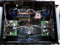
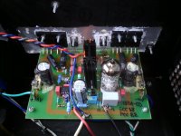
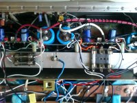
Leach with NJL in new chasis
My low TIM Leach amp in new chasis with big capacitors indoors.
My earlier chasis could not accomodate the big size capacitors and were fitted beneath the chasis, on the outside. I found an old instrument chasis that had enough height for thr caps to stand vertical.
My main aim behind laying the parts as are, was shortest possible connections. I may not cut the little extra lengths on the wires for want of servicing ease.
Gajanan Phadte
Attachments
Could other members - using buffers - please chime in with their own experience and where placement and cable length has affected your overall system performance.
Thanks,
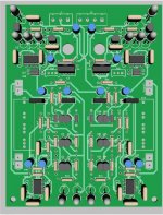
My "pitchfork" preamp will have the line buffer included (below).
With -200db PSRR and 1ppm THD20 , I would never throw it in
with my "slewmaster" power amp.
It would not take much EMI or inductive coupling to degrade those specs.
Plus , the 10 ohm output impedance will assure even poor interconnects
will perform.
OEM "integrated amps" often include a pre-buffer to accommodate the wide
array of inputs - but this is a separate "pro" system - not OEM consumer fare.
OS
Attachments
- Home
- Amplifiers
- Solid State
- Post your Solid State pics here