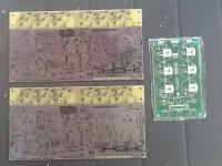
First One modules transformed into VSSA chassis. It is enough compact?
Are the amplifiers stacked so that one pair is hidden?.............Well thought out, good board work, nice assembly................
... Four amps, two per channel, ............

First One modules transformed into VSSA chassis. It is enough compact?
Simply Beautiful....
First One modules transformed into VSSA chassis. It is enough compact?
VERY nice build!

Might be a difference. Don't know if it will be a just discernible audible difference, or a measurable difference, or both. Or maybe no difference.
How could be any discernable or measurable difference when using quality, gold plated, high current-low resistenace, non rusted connectors?
You're always welcome.I know that you are very close to Papa
Best oscilloscope ever must watch
https://www.facebook.com/photo.php?v=306838556110583
https://www.facebook.com/photo.php?v=306838556110583
Next project: Goldmund Mimesis Clone
Boards arrived 10 minutes ago, thanks to Linvalb who had a spare pair of boards for me
I'm excited to start!
Are the board soldermasked? clear color? new to me.
SKA GB150D
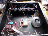
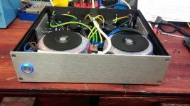
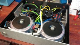
My first DIY project ..Dual mono construction, 2x 300VA toroidal transformers, dual rectifier PSU, 8x 12 000uf Epcos...
My first DIY project ..Dual mono construction, 2x 300VA toroidal transformers, dual rectifier PSU, 8x 12 000uf Epcos...
Attachments
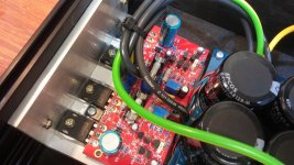


This circuit ... but some minor adjustments to my style.
An externally hosted image should be here but it was not working when we last tested it.
Oh ... thank you very much.Tiger,
the heatsinks are facing the wrong direction.
The ends where the air could enter to assist with cooling are blocked off.
I forgot about the direction heatsinks
Circuit
Ah ok! Thanks for sharing. How does it sound??
This circuit ... but some minor adjustments to my style.
An externally hosted image should be here but it was not working when we last tested it.
Ah ok! Thanks for sharing. How does it sound??
Ah ok! Thanks for sharing. How does it sound??
The overall sound as ok.
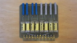
impedance input 100K
gain 20
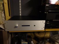
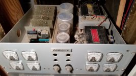
Power Amplifier with 1 kW Regulated Power Supply
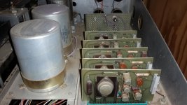
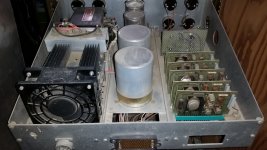
This is my first power amplifier started when I was in high school; the amp was built from 1966 to 1968. Both chassis are made with scraped semiconductor test equipment from Fairchild Semiconductor, they needed room for the new uA709 tester. I made the front panels form blank rack panels. Most of the other components were purchased at various surplus stores.
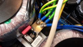
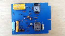
The power supply has 5 regulated outputs; +/- 50 V @ 10 A, +/- 15 V @ 500 mA and 24 V @ 1 A. The regulator boards were etched with a process I developed using contact photographic negatives and ferric chloride on a hotplate with a bubble etch tank.
I designed a nonlinear current foldback circuit, which charged the 10,000 uF caps at a constant current of 1 A until the voltage reached 45 V, then increases to 10 A as the voltage reaches 50 V. This limits the capacitor inrush current until the end of the charge time. The +/- 50 V and +/- 15 V supplies are floating in the power supply chassis and are only connected together at one point with a ½” x ½” brass common bus bar in the power amp chassis. The first board in the power supply chassis is an auxiliary power supply, which is not switched off with the line power relay. It provides the line power relay with 12 VDC for remote power switch in the power amp chassis.
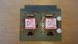
The input relay board has trim pots to set all the levels individually. The RIAA phone equalizer board amplifiers are discrete Intech Op-Amps. They are low noise FET input amplifiers with a 10 MHz bandwidth. The Intech A-148 amplifier was designed around 1965 and is the same basic circuit as the 990 Discrete Op-Amp, except for the FET input stage and inductors.
The power amplifier is a quasi-complementary symmetry design. All boards were designed to take advantage of the 22 pin edge card connectors, which allows interchangeability, bench troubleshooting and testing. Many years later I built a power amp test fixture also using 22 pin edge card connectors.
This is my first power amplifier started when I was in high school; the amp was built from 1966 to 1968. Both chassis are made with scraped semiconductor test equipment from Fairchild Semiconductor, they needed room for the new uA709 tester. I made the front panels form blank rack panels. Most of the other components were purchased at various surplus stores.
The power supply has 5 regulated outputs; +/- 50 V @ 10 A, +/- 15 V @ 500 mA and 24 V @ 1 A. The regulator boards were etched with a process I developed using contact photographic negatives and ferric chloride on a hotplate with a bubble etch tank.
I designed a nonlinear current foldback circuit, which charged the 10,000 uF caps at a constant current of 1 A until the voltage reached 45 V, then increases to 10 A as the voltage reaches 50 V. This limits the capacitor inrush current until the end of the charge time. The +/- 50 V and +/- 15 V supplies are floating in the power supply chassis and are only connected together at one point with a ½” x ½” brass common bus bar in the power amp chassis. The first board in the power supply chassis is an auxiliary power supply, which is not switched off with the line power relay. It provides the line power relay with 12 VDC for remote power switch in the power amp chassis.
The input relay board has trim pots to set all the levels individually. The RIAA phone equalizer board amplifiers are discrete Intech Op-Amps. They are low noise FET input amplifiers with a 10 MHz bandwidth. The Intech A-148 amplifier was designed around 1965 and is the same basic circuit as the 990 Discrete Op-Amp, except for the FET input stage and inductors.
The power amplifier is a quasi-complementary symmetry design. All boards were designed to take advantage of the 22 pin edge card connectors, which allows interchangeability, bench troubleshooting and testing. Many years later I built a power amp test fixture also using 22 pin edge card connectors.
Attachments
post3635:The overall sound as ok.
impedance input 100K
gain 20
the pic shows input impedance = 52k (51k+1k).
Not 100k.
The gain is shown as 51 (1+50k/1k).
Not 20.
Did you build what you have posted?
- Home
- Amplifiers
- Solid State
- Post your Solid State pics here