20 years old chip wine
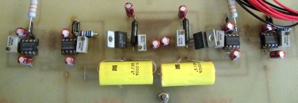
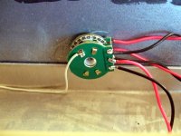
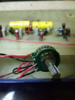
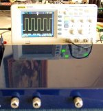
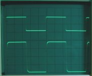
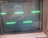
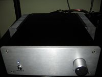
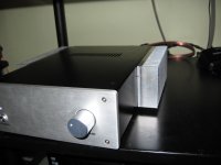
A 20 years old chip preamp this one. Came for changing log pot from the friend I had given it a long time ago. It is an OPA627 unity gain buffer feeding an OPA637 X6 gain stage sandwiching the volume control. Fully DC coupled with offset trimmers for each stage. Had made a large hand drawn PCB for it back then including routing for many inputs and rec out select all the way back to a row of RCA's meeting the board. Had simply cut out some aluminum panels and put it together with stainless steel screws and Fender Tele knobs. Automotive paint job non the less. I remember to had selected the 627-637 just from a BB brochure on intuition. Too expensive to stock, the official representative company had told me in yr 1991. Two months on the wait on special order and many dollars for the era... Very good passive components like Holco and Vishay, separate PSU, Teflon silver wiring, and what do you know, still measures and sounds clean as a whistle, and smooth. Especially with the new pot, very good imaging. Can pass a very nice 200kHz square wave, won't clip before 29V Pk-Pk sine wave, FFT attached (0dBFS=2VRMS). Nice to preserve an oldie.")
A 20 years old chip preamp this one. Came for changing log pot from the friend I had given it a long time ago. It is an OPA627 unity gain buffer feeding an OPA637 X6 gain stage sandwiching the volume control. Fully DC coupled with offset trimmers for each stage. Had made a large hand drawn PCB for it back then including routing for many inputs and rec out select all the way back to a row of RCA's meeting the board. Had simply cut out some aluminum panels and put it together with stainless steel screws and Fender Tele knobs. Automotive paint job non the less. I remember to had selected the 627-637 just from a BB brochure on intuition. Too expensive to stock, the official representative company had told me in yr 1991. Two months on the wait on special order and many dollars for the era... Very good passive components like Holco and Vishay, separate PSU, Teflon silver wiring, and what do you know, still measures and sounds clean as a whistle, and smooth. Especially with the new pot, very good imaging. Can pass a very nice 200kHz square wave, won't clip before 29V Pk-Pk sine wave, FFT attached (0dBFS=2VRMS). Nice to preserve an oldie.
Attachments
I gave the aluminum panels to a mate that was working in a paint shop at the time. And he used some leftover paint from when he had done his Vespa scooter. Really. Then it got renewed 15yrs later by the guy I gave it to. In an automotive paint shop. Check out how it reflects. Good in squares too. That one was a 20KHz square.
Really. Then it got renewed 15yrs later by the guy I gave it to. In an automotive paint shop. Check out how it reflects. Good in squares too. That one was a 20KHz square.Attachments
Salas: Other than those two buggers / harmonics @ 2k, ~3.3k ... ~120++ db down, all the way across, is still very impressive. All that plus a clean 20k square wave passthrough ...
Maybe a "re-visit" to this design is in order ... using plastic caps around the newer op-amps and other tweaks? (I might like to have one, me-self. )
Maybe a "re-visit" to this design is in order ... using plastic caps around the newer op-amps and other tweaks? (I might like to have one, me-self.
)
Last edited:
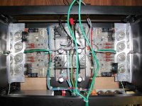
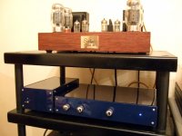
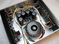
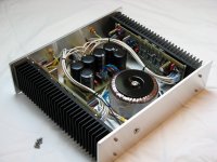
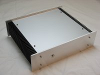
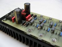
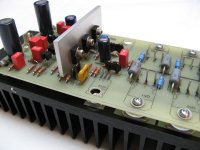
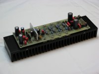
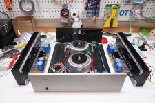
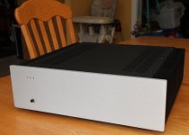
This one would have been a plain Blameless, but ended up a derivative of the DIYAmp (PCB layout is my own, transformer is only a 30-0-30 V unit).
http://www.diyaudio.com/forums/solid-state/192431-class-ab-amp-diyaudio.html
The performance is as promised. Big thanks to OS!
Case top and bottom are 2mm anodized aluminum sheets.
Front and back are sanded 100x6mm aluminum flat bar.
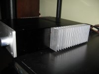
Heat sinks are Modushop/Hifi 2000 300x80mm, drilled and tapped 8-32 to hold the six sides together.
The power devices leads will be trimmed flush. They were left in case the mounting arrangement had to be changed.
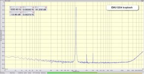
The FFT was done with an emu0204 unit and has to be taken for what it is worth.
The 60/180/300/420/540 Hz noise visible seems to be coming directly from the transformer. It can be canceled almost totally by rotating the toroid around its bolt, at the expense of the other channel. Both channels are audibly silent.
http://www.diyaudio.com/forums/solid-state/192431-class-ab-amp-diyaudio.html
The performance is as promised. Big thanks to OS!
Case top and bottom are 2mm anodized aluminum sheets.
Front and back are sanded 100x6mm aluminum flat bar.
Heat sinks are Modushop/Hifi 2000 300x80mm, drilled and tapped 8-32 to hold the six sides together.
The power devices leads will be trimmed flush. They were left in case the mounting arrangement had to be changed.
The FFT was done with an emu0204 unit and has to be taken for what it is worth.
The 60/180/300/420/540 Hz noise visible seems to be coming directly from the transformer. It can be canceled almost totally by rotating the toroid around its bolt, at the expense of the other channel. Both channels are audibly silent.
Attachments
-
 ssfft emu0204 loopback, -12dB in_cr.jpg98.6 KB · Views: 343
 -
 ss01 fft blame L, 10V, 10ohm, ifbox-20dB.png120.2 KB · Views: 641
 -
 ssIMG_3836.JPG96.2 KB · Views: 851
 -
 ssIMG_3825.JPG98.9 KB · Views: 875
 -
 ssIMG_3813.JPG98.9 KB · Views: 699
 -
 ssIMG_3812.JPG63.6 KB · Views: 633
 -
 ssIMG_3808.JPG89.6 KB · Views: 663
 -
 ssIMG_3804.JPG101.4 KB · Views: 799
 -
 ssIMG_3801.JPG77.3 KB · Views: 913
also a beauty, very low thd, but how it sounds with so low thd because the first and second harmonic is importand for the amp character, maybe this one sounds very lean?
what do you use for measurement? of thd, I look for good software and mike.
it is beautifull made.
regards
what do you use for measurement? of thd, I look for good software and mike.
it is beautifull made.
regards
Salas: Other than those two buggers / harmonics @ 2k, ~3.3k ... ~120++ db down, all the way across, is still very impressive. All that plus a clean 20k square wave passthrough ...
Maybe a "re-visit" to this design is in order ... using plastic caps around the newer op-amps and other tweaks? (I might like to have one, me-self.
I believe that the 10uF Stargets decouple it fine, there is no ringing in square waves, and there is no glassiness subjectively. A parallel regulator would make it more juicy. I must be having the hand drawn layout ''modules'' around the chips somewhere, but I could not readily find them to post them for you.
also a beauty, very low thd, but how it sounds with so low thd because the first and second harmonic is importand for the amp character, maybe this one sounds very lean?
what do you use for measurement? of thd, I look for good software and mike.
it is beautifull made.
regards
To me it sounds great - but I have tin ears
I do believe the speakers to be the bottleneck in the chain though.
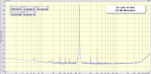
The measurement is done using an E-MU0204 USB DAC/ADC unit at 24bit/192kHz:
E-MU 0204 USB
The input is routed via a homemade 0/-10/-20/-30/-40 dB attenuation box with zener clamps to protect the ADC.
The ADC can only take 2 Vrms maximum, so I use 20 dB attenuation in that graph. The software is SpectraPlus. The numbers shown on the graph do not mean much - the E-MU runs out of steam above 30 kHz.
10 V, 20 kHz square wave into 10ohm/47nF attached.
Attachments
Last edited:
To me it sounds great - but I have tin ears
I do believe the speakers to be the bottleneck in the chain though.
The measurement is done using an E-MU0204 USB DAC/ADC unit at 24bit/192kHz:
E-MU 0204 USB
The input is routed via a homemade 0/-10/-20/-30/-40 dB attenuation box with zener clamps to protect the ADC.
The ADC can only take 2 Vrms maximum, so I use 20 dB attenuation in that graph. The software is SpectraPlus. The numbers shown on the graph do not mean much - the E-MU runs out of steam above 30 kHz.
10 V, 20 kHz square wave into 10ohm/47nF attached.
Thank you, I will try that also.
it is more clean then what I have now.
To me it sounds great - but I have tin ears
I do believe the speakers to be the bottleneck in the chain though.
The measurement is done using an E-MU0204 USB DAC/ADC unit at 24bit/192kHz:
E-MU 0204 USB
The input is routed via a homemade 0/-10/-20/-30/-40 dB attenuation box with zener clamps to protect the ADC.
The ADC can only take 2 Vrms maximum, so I use 20 dB attenuation in that graph. The software is SpectraPlus. The numbers shown on the graph do not mean much - the E-MU runs out of steam above 30 kHz.
10 V, 20 kHz square wave into 10ohm/47nF attached.
Square waves give a sample of how fast the amp is, but the most modern parts can do even 500 khz with no problem, what is important, yes the overshoot, it a square wave lets see this then it sound hars, of how you call that in english, the amp needs speed and a very good break like a fast car, then it will be sound 3D. even a slower good designed amp sounds better then a bad fast one with a bandwith of 1 Mhz, the best way I have experience with is current feedback or no feedback, current feedback is independent of bandwith that is the beauty of it and it has good breaks like a porsche.
see picture of dc coupled tube/mosfet amp, 50 khz wave, no feedback version.
Attachments
Last edited:
I have tryed with spectraplus, with the onboard audio chip but it has a lot of garbage already I can not measre with it because it has its own distortion who is quite high (0.1) and much noise even without connection.
I have now the resistors for the attenuator so I go make that first..
I have now the resistors for the attenuator so I go make that first..
Attachments
Last edited:
from Canada..... lumieux is his name...be is building a Dx Blame MKIII Hx ... boards from our forum group buy.
regards,
Carlos
That is some serious heavy stuff, very nice
Yes Dias.... Cannonica is one of the best guys we have
Cannonica MKIII Hx built - YouTube
Great job he did.
regards,
Carlos
Cannonica MKIII Hx built - YouTube
Great job he did.
regards,
Carlos
Attachments
Junie from Dubai and Canonnica from Quebec
produced a very nice amplifier, they made a beautifull enclosure to install the MKIII Hx inside.... here some images inside this video:
http://www.youtube.com/my_videos?feature=mhee
Dubai is Arabian Emirates... and Quebèc is french Canadá
regards,
Carlos
produced a very nice amplifier, they made a beautifull enclosure to install the MKIII Hx inside.... here some images inside this video:
http://www.youtube.com/my_videos?feature=mhee
Dubai is Arabian Emirates... and Quebèc is french Canadá
regards,
Carlos
- Home
- Amplifiers
- Solid State
- Post your Solid State pics here