I have a preamp that I need a decent emitter-follower output stage for. The pic here is what I have come up with.
I need the gain provided by the Szilaki configuration. At Doug Self's site, he says " The value of Rc is crucial to good linearity, as it sets the Ic of the first transistor, and also determines its collector loading. The value of 3K3 shown here is a good compromise. " So I stuck with the 3.3K value, even though my collector current is at about 4mA as opposed to the 6mA in his described circuit.
If the value of Rc is so critical, how is its value derived? Nothing I have been able to find anywhere describes what variations in Rc may do to the circuit...any Guru's here care to elaborate??
Thanks all...
Attachments
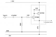
R is calculated by dividing Vbe (approximately 0.7v) by Ic1, where you assume that Ib2 is negligible. If you change it, the output offset voltage will change, Ic2 will also change. You have to set the value so that both transistors are well turned on given the 4.7K value of the emitter resistor and the negative rail voltage. With the values you show here, you're running about a quarter ma through the first transistor.
3k3 gives about 0.200 mA
in the first transistor.
I think you have made a good selection
for output configuration.
It gives High input impedance.
In fact this is how I would do it too.
For higher output currents, you can add a constant current source
with same configuration. Foldback.
0.200mA is about 1/20 or 1/25 of the output current.
Should work well.
I should think you can use up to 0.5mA without any
bigger change of performance.
I often myself like some more current,
at least 1/10 of the current in second transistor.
But I imagine this is dependent of which transistor you use,
and what your goal is. Low Noise or High Bandwith (fast).
-----------------
I guess you have an Input Capacitor in the circuit
that is driven by the output.
So the -0.7 V DC-offset, will not matter at all.
/halo - uses mostly BC550C and BD140 (or BC337)
::Light bulb pops on over head::
Sooo..., what we are concerned with (somewhat) is a ratio of Q1 current with Q2 current....the current through Q1 being calculated by Vbe/Rc.
In other words, decide on a value of Ic for Q1, then calculate an appropriate collector resistor.
Then I guess it just boils down to a decision on collector current for Q1. Rule of thumb here? halojoy says he likes 1/10 of the value of Q2 current or so...any other thoughts?
All I am concerned with as far as bandwidth is the audio range (and a bit more for headroom), so 40-50Khz is fine by me. Low noise and linearity is more important in this stage.But I imagine this is dependent of which transistor you use,
and what your goal is. Low Noise or High Bandwith (fast).
Yes...this feeds into a diff-amp (LTP) with a 1.2uF polypro cap for input...sorry, missed that last bit.I guess you have an Input Capacitor in the circuit
that is driven by the output.
So the -0.7 V DC-offset, will not matter at all.
Hate replying to my own damn threads...perhaps someone will chime in 
Built and installed the circuit as shown in the original post. Works much better than the simple emitter-follower, but voltage readings are off a little...
Base of Q1 has about -.3V on it...expected to see about -.1V. Output (top of Re) is at about -.9V...expected about -.7 or so.
What this means is that the overall current gain of the Szilaki configuration is not a product of the two transistors. Overall gain is about 4000. Even with a measily hfe of 100 or so, if gain was a product of Q1*Q2, then current gain would be around 10,000.
So, this Rc feedback config obviously reduces current gain...but probably increases linearity. I'm betting that different values of Rc vary the overall current gain quite a bit, but not going to fool with it now that it is up and running.
To get the voltage values I expected, I would probably have to reduce the 300K base biasing resistor. Unfortunately I can't, as there is a subsonic filter in the preceeding stage that requires a high input impedence at this stage, and the 300K resistor is needed. Looked at the variation with a current source, but the increased complexity on my board makes it difficult to implement. I'll stay with this circuit.
Regardless, this stage will probably never see much more than 4V P-P signal to drive the amp to full output, and I'm hoping the circuit has reduced harmonics considerably. All in all, a good learning experiance.
Question: Is there any way to calculate current gain with this config...taking into account the value of Rc? It is the last part of the equasion that I'd like to solve...
Input & output
Yes, that was what I wondered,
if you needed such large input impedance.
The bias current to the base of T1
will make some noise in 300k resistor.
I call this circuit (and amplifiers) for adaptor.
You have one device, want to connect it to another.
You need somthing in between.
This is an adaptor.
--------------------------------------------------
We need so much
info about output of the source-circuit
and the info about input of the second circuit
AS POSSIBLE.
Then we can start building the adaptor circuit.
-------------------------------------------------------
You cannot start discussing an adaptor(amplifier)
by itself. If it is good or bad.
It ALL depends on What is before and after.
What is connected to the input
and what is conneted to the output.
I am sorry to dissapoint you - but Amplifiers Are a (somtimes) Nessesary Evil
An ADAPTOR between a Source & a LOAD
you do not have to believe me,
but this is how it is
says clever halojoy of sweden alias gromanswe
www.geocities.com/halomatics
www.geocities.com/gromanswe

- Status
- This old topic is closed. If you want to reopen this topic, contact a moderator using the "Report Post" button.
- Home
- Amplifiers
- Solid State
- Help a nOOb out with an emitter-follower...