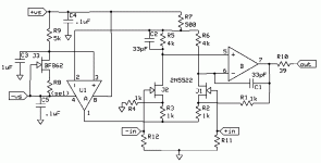
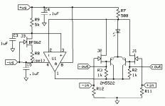
Here’s a “nice little preamp” that gives differential or single ended inputs to a single ended output. It’s based on the original SSM preamps.
Advantages; noise can be pretty low at low gains as well as high gains. U1-A works essentially only on the common mode signal and U1-B is desensitized by 10dB or so even at 6dB gain and more at higher gains. There are no “pull down” current sources to contribute noise and/or distortion. Both inputs can be very high R so coupling caps can be low value film even for very low frequencies.
Disadvantages; 6dB is the min. gain and the opamps need to have a common mode range sort of close to the + rail. The common mode input range is OK but not as large as one might want.
I build this with AD823’s and tested it at G = 2 and it looked pretty good (and it didn’t oscillate). It simulates at about 10nV/rtHz RTO noise and RTI at however good a FET you put in the input. So your talking <3nV RTI even at a gain of only 10. The output went ~+-7V from a couple of 9V batteries (~8.5V left). Distortion looked good (.005%) but I used a USB DAC to get an input signal and not an instrument. You could cascode the FETs for marginally better performance I suppose, but it makes the common mode range issue more difficult unless the supplies are at a higher voltage. You could also trim offset via the 4K resistors without compromising any other performance. My breadboard used closest 1% values for everything.
As with the charge amp idea this is offered freely for any use.
EDIT - Sorry I forgot, the gain is set by a resistor between the sources of the input FET's (~200 Ohms for 20dB and 20 for 40dB)
Attachments
Hi Scott!
Me again.
Again, thank you for sharing your design. I see you are using batteries to supply the preamp and that the results you're getting are quite good. I'm wondering what the preamp's PSRR is, though. Also, in your opinion, what would be a suitable power supply design if the preamp were to be supplied with standard +/-17V? The FET you are using is unavailable to me so I'd also appreciate some tips on what you'd consider as adequate substitutes.
Regards,
Milan
the right part of this circuit
is well known.
You use 2 low noise transistors in differential
each one feeds input pin of op-amp.
So we have added one more stage, input stage, to the Op-amp.
This can be good when need very low noise and high gain.
The open loop gain will increase with gain of transistors
I used this type of circuit, when I built one MIC amp
with closed loop gain of x100 and fed by one 9 volt battery.
( I used a BC550C pair + NE5534 Op-amp.
Should better have been two BC560C, I think today. )
this mic amplifier still works very well
what is more new to me, is the left Op-amp.
seems like it controls the operation points of the other part.
In 2 ways.
Two controls in one.
lineup
The left opamp controls the current in the FET pair (actually bipoars work too) to about 1-1.2mA per side and removes the common mode voltage at the input at the same time. This makes a true instrumentation amplifier configuration which is actually quite different than the diff-pair opamp composite configuration. You now have symetrical inputs which can be used as single ended or differential input of either polarity. The current source biasing the whole this is not that critical, for the ultimate in PSRR you could make things a little better. I'm trying to make a battery powered rig for doing some nature recording in the field and other than noise I think everthing else is a diminishing return. Any decent FET dual should work. I'm actually going to try and build up one with selected singles and see if the DC stability holds up after I trim it (a large resistor in parallel with one or the other of the drain loads selected for 0 offset at the output).
lineup said:
what is more new to me, is the left Op-amp.
seems like it controls the operation points of the other part.
In 2 ways.
Two controls in one.
lineup
By monitoring the total current in the pair, any change in this is reacted to by the CCS(U1-A) and should help the CMRR.
The 'ugly amp' I made does somthing somewhat similar but with descrete parts, where the bias of the first diff stage is dependent on the second stage diff(VAS) CCS bias and adjusts the first stage CCS bias to correct any difference in overall current to the second diff pair, via a simple feedback loop using a p-channel j-fet(MMBF5461) to feedback to the source resistor on the first stage CCS, which should be constant for better CMRR in second stage as well as first. Seems very stable.
stoolpigeon said:Hi Scott,
I have a couple of queries about this circuit:
Could an LM394 be used at the input?
Any thoughts on its suitability as first stage of a balanced mm phono amp?
Thanks!
No problem, I've tried it with MAT02's. I'd stick with FET's for mm. The net benefit depends on your source impedance over frequency. I use Grado (MI) so the difference is less striking, but a classic Shure type has a huge noise peak due to current noise with biploars. There is a nice National appnote on this, probably still available. Also the RIAA is problematic, I'm not sure how I would work in the time constants for this circuit. You could configure the first two time constants as active differential at a little more expense, with a passive third one at the output.
Double parallel Mat02's would probably make a decent MC front end. Here you would just have gain in front of a normal single ended RIAA stage.
Disadvantages; 6dB is the min. gain
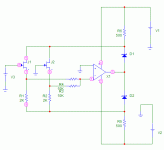
Will this circuit work as a differential follower?
Attachments
dimitri said:
Will this circuit work as a differential follower?
??? You're not getting rid of the common mode voltage anymore, I'm not quite sure if this circuit would be useful.
- Status
- This old topic is closed. If you want to reopen this topic, contact a moderator using the "Report Post" button.
- Home
- Amplifiers
- Solid State
- A nice little preamp


 my bad. This one works but have very limited input range as the voltage swing at nodes 5 and 9 is too high...